Facebook
 Google
 GitHub
 Linkedin
Hi folks
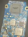
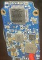
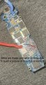
these boards are pretty nifty, acessability Is great, just download the ide flash via usb and your set to go.
They are a vape, the aegis x.
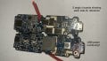
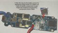
the microcontroller that allows all this is from Panasonic owned nuvaton whom have released they’re own ide for programming but also a way to easily convert to arduino 1.5.8. The chip can function without a crystal, has multiple clocks and has a Pwm frequency into the 140mhz range.
I found the idea of vaporising water with a peizo disc directly from a chip that dosnt require a crystal every 60 seconds pretty weird.
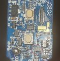
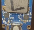
But jokes Aside there is a huge amount of potential in a hefty power distribution board like this.
here’s the data sheet for the microcontroller for those intrested:
https://www.nuvoton.com/resource-files/TRM_NUC200_220(AN)_Series_EN_V1.02.pdf
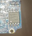
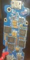
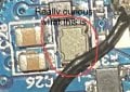
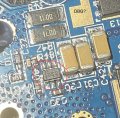
what I wanted to ask is could anyone help with an electronic component search engine or a nod in the right direction, maybe your knowledge could make a difference as I search for the data sheets and to identity so many little black chips amongst a sea of diodes capacitors and resistors.
if I knew what I was looking at researching and experimenting in how programming is achieved would be a fun and interesting project.
datasheets:
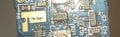
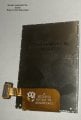
screen
LCM Driver IC: ST7789V
https://www.globalsources.com/product/tft-lcd_1173221463f.htm
these boards are pretty nifty, acessability Is great, just download the ide flash via usb and your set to go.
They are a vape, the aegis x.
the microcontroller that allows all this is from Panasonic owned nuvaton whom have released they’re own ide for programming but also a way to easily convert to arduino 1.5.8. The chip can function without a crystal, has multiple clocks and has a Pwm frequency into the 140mhz range.
I found the idea of vaporising water with a peizo disc directly from a chip that dosnt require a crystal every 60 seconds pretty weird.
But jokes Aside there is a huge amount of potential in a hefty power distribution board like this.
here’s the data sheet for the microcontroller for those intrested:
https://www.nuvoton.com/resource-files/TRM_NUC200_220(AN)_Series_EN_V1.02.pdf
what I wanted to ask is could anyone help with an electronic component search engine or a nod in the right direction, maybe your knowledge could make a difference as I search for the data sheets and to identity so many little black chips amongst a sea of diodes capacitors and resistors.
if I knew what I was looking at researching and experimenting in how programming is achieved would be a fun and interesting project.
datasheets:
screen
LCM Driver IC: ST7789V
https://www.globalsources.com/product/tft-lcd_1173221463f.htm
Attachments
-
 182.1 KB Views: 8
 -
 739.5 KB Views: 8
 -
 232.3 KB Views: 8
 -
 1.5 MB Views: 8
 -
 2.2 MB Views: 8
 -
 389.5 KB Views: 7
 -
 276.6 KB Views: 7
 -
 330.2 KB Views: 7
 -
 655.1 KB Views: 7
 -
 1.1 MB Views: 7
Last edited:
 anyone help?