Facebook
 Google
 GitHub
 Linkedin

All credit for this project goes to Raymond Genovese. His project can be found at https://www.allaboutcircuits.com/projects/build-an-arduino-controlled-am-fm-sw-radio/ where the full project description can help in understanding my problem. I am trying to make an AM/FM radio with an Arduino UNO and Si4844-B20 chip. The data sheet for the chip can be found at https://www.silabs.com/documents/public/data-sheets/Si4844-B20.pdf. I am using a logic level converter (5v to 3.3v) for the SDA, SCL, INT, and RST pins (Sparkfun). I also converted TWBR=198 for 10kHz and TWBR=38 kHz for 50kHz to accommodate for the 16kHz vs 8kHz difference between the Pro Mini and UNO. I went over the updated circuit three times and it is exactly the same as the picture (updated). In addition, every solder joint has continuity. I cannot get the I2C communication to work and keep getting the following feedback with the incorrect band mode and I should be getting radio frequencies:
*** Si4844 Quick Test **
...setting I2C speed to 10kHz
...resetting Si4844
Si4844 reset complete
...sending ATDD_POWER_UP with band set
Si4844 ATDD_POWER_UP completed
...setting I2C speed to 50kHz
...sending ATDD_GET_STATUS
...completed - tuner information is ready
Band Mode is 3 [0=FM 1=AM 2=SW]
Band Index is 31 [0-19 FM / 20-24 AM / 25-40 SW]
Tuner Frequency (mHz)= 151515.15
Chip information…
Final two digits of part number: 255
Firmware revision: ⸮.⸮
Component revision: ⸮.⸮
Chip revision: ⸮
Entering tuning loop…
151515.15
151515.15
151515.15
151515.15
151515.15
151515.15
151515.15
151515.15
151515.15
151515.15
151515.15
The circuit diagram is shown below, as well as my circuit and modified code:
SDIO: Purple (SDA)
RST: Green (12)
SCLK: Orange (SCL)
IRQ: Blue (2)
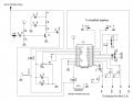
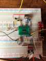
*** Si4844 Quick Test **
...setting I2C speed to 10kHz
...resetting Si4844
Si4844 reset complete
...sending ATDD_POWER_UP with band set
Si4844 ATDD_POWER_UP completed
...setting I2C speed to 50kHz
...sending ATDD_GET_STATUS
...completed - tuner information is ready
Band Mode is 3 [0=FM 1=AM 2=SW]
Band Index is 31 [0-19 FM / 20-24 AM / 25-40 SW]
Tuner Frequency (mHz)= 151515.15
Chip information…
Final two digits of part number: 255
Firmware revision: ⸮.⸮
Component revision: ⸮.⸮
Chip revision: ⸮
Entering tuning loop…
151515.15
151515.15
151515.15
151515.15
151515.15
151515.15
151515.15
151515.15
151515.15
151515.15
151515.15
The circuit diagram is shown below, as well as my circuit and modified code:
SDIO: Purple (SDA)
RST: Green (12)
SCLK: Orange (SCL)
IRQ: Blue (2)
Attachments
-
92.2 KB Views: 46