Arduino Uno ADC accuracy

Thread Starter

ebeowulf17

Joined Aug 12, 2014
3,307
I'm curious what level of accuracy people can generally expect from microcontroller ADC inputs.

I've been working on a current measurement project which gave me inconsistent readings, especially at the bottom end of the input range, so I did some tests to assess my ADC accuracy.

A few notes:
  • All of the measurements were done with a simple voltage divider trim pot as the test signal, not my current measurement circuit which could potentially have inconsistencies of its own.
  • The Arduino was running 64x over sampling, theoretically delivering the equivalent of 13 bit resolution from the Uno's 10 bit converters. I did other tests and examined raw readings to confirm that the over sampling was working properly.
  • The Arduino was powered with a 9V input, and the 5V internal power system (also used as Aref) measured exactly 5.00V every time I checked throughout the tests.
  • External voltage measurements were performed with an Extech EX330 multi meter.
The error level of the Arduino ADC (assuming the Extech was accurate) varied from around -12mV at the lowest input voltages to +7mV around 4V, then back down to almost -5mV just before 5V. At min and max of 0 and 5V, it correctly read 0 and 5000mV.

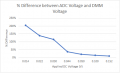
Although the actual amount of error is only a little worse at the bottom end of the scale than in other regions, the error as a percentage of the measured value gets ridiculous. Being off by >10mV on a 20mV signal is really bad!

For the moment, my lesson here is that I should not take any reading below 100-200mV very seriously! I'm curious what you all think of these error levels. Does this seem normal?

IMG_4282.PNG
 

WBahn

Joined Mar 31, 2012
29,979
The EX330 on the 4 V range is ±1% of reading plus 2 digits, so near full scale that's ±42 mV. On the 40 V scale, that's ±60 mV. So there's isn't much you can really say based on the measurements.

Having said that, it is very hard, in general, to keep digital noise out of analog measurements. We found that getting 12 bits of actual, reliable accuracy required pretty serious layout efforts, including making our own standard cell libraries that did NOT use the substrate ties on the ground lines, but rather routed digital ground and substrate/well ties for digital sections back separately in metal. Very few foundry libraries do this. We also controlled the speed of the clock and digital logic edges, though this is fairly common. To get much better than that required doing correlated double sampling and at some point required suspending the clock and nearly all digital activity during the sensitive part of the measurement cycle.

Some of these things are predominantly NRE annoyances, but others impact die size, operating speed, and operating complexity. So there's a limit to what can be reasonably expected from ADC/DAC capabilities on something like an MCU that has tons of other digital stuff going on at the same time.
 

smooth_jamie

Joined Jan 4, 2017
107
This is interesting. I made a current monitoring project and I compared the built in Arduino ADC with an ADS1x15 ADC breakout. I was interesting in measuring 1-100mA with 1mA resolution. Separating analogue and digital lines are tricky and ground loops cause problems.

I would suggest looking at what accuracy your aiming for regarding your monitoring project, and use your ADC with that in mind. In my case I was able to compensate for any errors by deriving a third order polynomial trendline from empirical data in excel and using the trendline formula to calibrate my code.

From looking at your graph in terms of Arduino vs DMM (%) you have a 0% difference between the two over 80% of the range, which seems quite good. If you are looking to measure at the low end you might want to consider some additional circuits (amplifiers etc) to create measurements ranges to get the accuracy to something reasonable (perhaps to within 10%?)

Additional:
Just looking at my calibration results, they seem to concur with yours. Difference between a DMM and ADC measured value is easily within 2% for most of the range but increases significantly above 10% measuring at the very low end. If I have time I will do a short test tonight and share the results if anyone is interested.
 
Last edited:

Thread Starter

ebeowulf17

Joined Aug 12, 2014
3,307
This is interesting. I made a current monitoring project and I compared the built in Arduino ADC with an ADS1x15 ADC breakout. I was interesting in measuring 1-100mA with 1mA resolution. Separating analogue and digital lines are tricky and ground loops cause problems.

I would suggest looking at what accuracy your aiming for regarding your monitoring project, and use your ADC with that in mind. In my case I was able to compensate for any errors by deriving a third order polynomial trendline from empirical data in excel and using the trendline formula to calibrate my code.

From looking at your graph in terms of Arduino vs DMM (%) you have a 0% difference between the two over 80% of the range, which seems quite good. If you are looking to measure at the low end you might want to consider some additional circuits (amplifiers etc) to create measurements ranges to get the accuracy to something reasonable (perhaps to within 10%?)
Thanks! There isn't really a specific accuracy requirement on this project, cause I'm just playing with current transformers for fun and to learn how to work with them.

I'm using a transformer that's rated for up to 50A primary current, I've chosen a burden resistor to scale it for ~25A max in terms of the range I'll be able to read on a 5V system, and from there I've just been exploring the possibilities of how much resolution I can achieve, how small of currents I can measure, and what sort of accuracy I might be getting. None of this is critical - all just for fun and learning!

I had already started implementing a two range system of sorts to get better readings on the low end by switching parallel resistors in and out of the burden resistor portion of the circuit such that I'm effectively switching between 220R and 2k2 burden resistors, so I now have a ~2.5A range and a ~25A range. It was testing of this switch function that revealed the ADC questions, because measurements weren't moving by a factor of 10 as expected. DMM voltage measurements confirmed that the burden switching was working as expected, and that the error was primarily on the ADC side.

Now that I know the low end of this ADC range is not only lower resolution, but also much higher percentage of error, I may also employ a polynomial correction factor like you mentioned in order to clean up the low readings somewhat.

In the meantime, I'd love to hear more other people's experiences with ADC accuracy, particularly the ADCs that are built in to microcontrollers.
 

Thread Starter

ebeowulf17

Joined Aug 12, 2014
3,307
The EX330 on the 4 V range is ±1% of reading plus 2 digits, so near full scale that's ±42 mV. On the 40 V scale, that's ±60 mV. So there's isn't much you can really say based on the measurements.

Having said that, it is very hard, in general, to keep digital noise out of analog measurements. We found that getting 12 bits of actual, reliable accuracy required pretty serious layout efforts, including making our own standard cell libraries that did NOT use the substrate ties on the ground lines, but rather routed digital ground and substrate/well ties for digital sections back separately in metal. Very few foundry libraries do this. We also controlled the speed of the clock and digital logic edges, though this is fairly common. To get much better than that required doing correlated double sampling and at some point required suspending the clock and nearly all digital activity during the sensitive part of the measurement cycle.

Some of these things are predominantly NRE annoyances, but others impact die size, operating speed, and operating complexity. So there's a limit to what can be reasonably expected from ADC/DAC capabilities on something like an MCU that has tons of other digital stuff going on at the same time.
Thanks for sharing all that. Fascinating stuff. I'm glad there are people like you tackling the really tough problems so that people like me can just enjoy the luxury of having shockingly good performance compared to what we pay for these components.

I may always yearn for more, and I may nitpick about whatever imperfection any system has, but mostly I just marvel constantly at how much capability is available to the modern electronics hobbyist. I feel quite lucky!
 

MrSoftware

Joined Oct 29, 2013
2,188
Based on my own personal limited experience with the Extech brand; I wouldn't use one of their meters as a reference for anything. If accuracy and precision is required there better choices. Maybe look at a Fluke or something similar.

I don't want to hijack the thread, but here are a couple of good watches that will help you choose a better meter:


Danko

Joined Nov 22, 2017
1,829
For the moment, my lesson here is that I should not take any reading below 100-200mV very seriously! I'm curious what you all think of these error levels. Does this seem normal?
You can avoid most of errors and easy get accurate AVG readings from 0 to 50A with resolution 1mA.
Simple use converter Current--->Frequency and write or take existing sinometer program for Arduino or buy DIY counter for $10.10 at:
https://www.banggood.com/DIY-Freque...rmmds=detail-top-buytogether&cur_warehouse=CN
PDF - http://img.banggood.com/file/products/20160817023551SKU360318.pdf
For example, for current=50A and transformer 1:1000, after diode bridge, 50mA current charges/discharges converter's capacitor with average frequency 50 kHz, then sinometer will display 50.000 (A).
 

smooth_jamie

Joined Jan 4, 2017
107
OK so I was bored enough to do this quick test. I uploaded a simple analogRead sketch to an Arduino Nano to read analog pin 0 every second, applied a 0-5V DC voltage, and recorded the output of the serial monitor in a spreadsheet. I also took multimeter readings in parallel with the ADC value. I then calculated the voltage from the ADC value by the maximum readable voltage divided by the full-scale analog read resolution.

In this case I noticed the analog input gave the maximum integer of 1023, with a voltage of 4.7V (not 5V as expected), so I factored that into the calculation for the derived ADC voltage measurement. Please find attached the speadsheet of results and a graph of the low end measurements.

You will notice that the % difference between ADC voltage and DMM voltage is already 10% at 150mV (this is a mental bracket for me, and a common tolerance I see in many places such as datasheets etc etc). At 50mV the error increases to 21%, the error reaches 115% at 30mV, and at 14mV the discrepancy reaches a maximum of 204%

In conclusion it depends on how low you want to measure, you can always boost small signals from CT's with an op-amp. You can also get 16-bit ADC's which give 32768 voltage steps (rather than the standard Arduino 1023).
 

Attachments

philba

Joined Aug 17, 2017
959
One thing to consider is the arduino layout is not good at all for analog. Very noisy. And if you have a solderless breadboard, it's even worse. So, you have to do some filtering of your results. Oversampling helps but you need to factor in how many LSBs you are down by.
 

Thread Starter

ebeowulf17

Joined Aug 12, 2014
3,307
One thing to consider is the arduino layout is not good at all for analog. Very noisy. And if you have a solderless breadboard, it's even worse. So, you have to do some filtering of your results. Oversampling helps but you need to factor in how many LSBs you are down by.
Yeah, I'm definitely seeing that. If I look at the raw ADC output, it dances around by 2 LSBs constantly, occasionally hitting 3-4 LSBs of movement. However, at least in this series of tests and experiments, the over sampling delivers surprisingly stable results for me.

I'm over sampling 64x, which theoretically delivers 13 bit equivalent resolution... but since I'm scaling the ADC output into 5000 steps (5V range, displaying 1mV output resolution,) I'm displaying ~12.3 bits of resolution... not much overhead.

In spite of the low overhead, I'm finding that about 90% of the voltages I read are rock solid, with the remaining readings alternating between just two adjacent values (1mV apart.) It probably helps that this is a battery operated project, not directly connected to anything else, and in a relatively low-noise environment.
 

Thread Starter

ebeowulf17

Joined Aug 12, 2014
3,307
I assume you understand that over-sampling only affects the resolution, not the measurement absolute accuracy.
Yes, definitely! I wish accuracy was as easy to solve as resolution. The world would be a much simpler place.

It does knock down the noise quite a bit too, although of course trading off response time. I suppose in terms of noise filtering it's a lot like a LPF (it's not doing anything for the accuracy of the average value, but it is knocking down high frequency noise so you can more easily see the potentially inaccurate average value.)
 

be80be

Joined Jul 5, 2008
2,072
Math on Adc with atmega kind of increases error tho from what i hear you lose a lot on the lowend. which kind of matches your test. Roman Black wrote a really good write up about adc.

This is what he wrote.
It's common to need to scale a microcontroller ADC result to give a value in some other scale. One example is to scale the ADC to read in actual volts like read from 0.00v -> 5.00v.

People sometimes use ADC *500 /1023 as this gives a reading of 500 (5.00v) for the top ADC value of 1023.


Doing that math; *x/(n-1) or *x/1023 does perform a kind of rounding function, but it "fudges" the rounding and gives both scaling and rounding errors.

The correct scaling math; *x/n or *x/1024 correctly scales all the output data in size, but gives an average rounding error of 0.5 ADC counts (always rounding down).

To magnify and show the errors caused by *x/(n-1) this table shows a simple ADC that has 5 values. (This is just like a PIC ADC but has 5 possible ADC values, not 1024).
Code:
b]First the incorrect *x/(n-1) math;[/b]
input       ADC math        result  average     output
voltage     value   ADC*x/(n-1)     error       result
4.00-4.99   4   *5 /4       5.00    +0.50       5
3.00-3.99   3   *5 /4       3.75    +0.25       3
2.00-2.99   2   *5 /4       2.50     0.00       2
1.00-1.99   1   *5 /4       1.25    -0.25       1
0.00-0.99   0   *5 /4       0.00    -0.50       0
Note that for the 5 possible ADC values, the output scale now has 6 values (0-5) and the value 4 can never occur! And although the average error might look to be nicely distributed +/- the centre of scale, the actual output result proves to be much uglier.

So if you had a slowly increasing voltage, the ADC would read; 0, 1, 2, 3, 5!!

The maximum error in real world use is 2v, because that very tiny change of 3.999v - 4.001v would cause an output change of 3v -> 5v or a change of 2v!
Code:
[b]Here is the correct scaling math *x/n;[/b]
input       ADC math        result  average     output
voltage     value   ADC*x/n         error       result
4.00-4.99   4   *5 /5       4.00    -0.50       4
3.00-3.99   3   *5 /5       3.00    -0.50       3
2.00-2.99   2   *5 /5       2.00    -0.50       2
1.00-1.99   1   *5 /5       1.00    -0.50       1
0.00-0.99   0   *5 /5       0.00    -0.50       0
All output values are properly scaled and all are represented. The average error is never greater than 0.5 (no more average error than the /(n-1) example), and the average error is always one fixed value (-0.5) making it very easy to compensate (see below).

The maximum error at any time is 1v, this is half the max error of the /(n-1) example, which can introduce extra error up to 1 in high value ADC readings.

Understanding the *x/(n-1) problem.

The problem with /(n-1) is that it corrupts the SCALING of data. Because it forces the top ADC unit value to be the top of the scale the scale no longer is an accurate conversion of data.

This corruption means the true scale of 1024:5 is being represented as 1023:5 so the data on the output is now larger than life;

All data is rounded down to the nearest ADC unit, so all the output data is correctly scaled but will have an average error of -0.5 ADC units.

This error is actually a property of the ADC module hardware AND the ratio scaling math. This is because the ADC hardware rounds all voltages down to the nearest ADC unit, and because the integer division (/1024) also rounds data down. (More on compensating for this later).

Here is the rest of the story
https://www.electro-tech-online.com...rect-and-adc-1023-is-just-plain-wrong.132570/
 
Last edited:

Thread Starter

ebeowulf17

Joined Aug 12, 2014
3,307
Just read the link above, thanks for posting it! Very interesting.

I am going to implement the method ((ADC*2)+1) *500 +1024 /2048 and see if this changes the results I posted earlier.
I don't think you're going to see much difference. The scaling error is 1023/1024, so less than 1/10th of 1 percent full scale.

The offset error due to using the wrong scaling method should (I think) be at most 2 LSBs, which is also far less than the error levels you've described finding in your ADC.

I'm not arguing against the math, just saying that the amount of error introduced is relatively small, compared to all the other possible sources of error.
 

smooth_jamie

Joined Jan 4, 2017
107
I'm not arguing against the math, just saying that the amount of error introduced is relatively small, compared to all the other possible sources of error.
Whoops, obviously I didn't think on about this. Having said that, if you can accomodate it in your micro controller, you may as well include it in your code.

Yes I suspect the discrepancy with the low end measurements in my case is probably due to random noise (as others have already pointed out).
 

Reloadron

Joined Jan 15, 2015
7,501
Guessing this thread is tied back to this thread with an ultimate goal of measuring AC current. Something else you may want to try in addition to oversampling is taking note of your actual reference voltage on the Arduino board. Then using that number in your code. For example when using an external power supply on one of my Arduino boards my Vref is actually 5.015 Volts. So if I measure voltage using 0 to 5 volts for example then I use code like this:
Code:
voltage = ((float)sum / (float)NUM_SAMPLES * 5.015) / 1024.0;
In the above I am also taking 10 samples but the idea is using 5.015 rather than 5.000. While it doesn't really matter much on some boards it helps. I use an external supply as my USB supply is not as stable as the 5 V regulator on the Arduino board.

Ron
 

Thread Starter

ebeowulf17

Joined Aug 12, 2014
3,307
Guessing this thread is tied back to this thread with an ultimate goal of measuring AC current. Something else you may want to try in addition to oversampling is taking note of your actual reference voltage on the Arduino board. Then using that number in your code. For example when using an external power supply on one of my Arduino boards my Vref is actually 5.015 Volts. So if I measure voltage using 0 to 5 volts for example then I use code like this:
Code:
voltage = ((float)sum / (float)NUM_SAMPLES * 5.015) / 1024.0;
In the above I am also taking 10 samples but the idea is using 5.015 rather than 5.000. While it doesn't really matter much on some boards it helps. I use an external supply as my USB supply is not as stable as the 5 V regulator on the Arduino board.

Ron
It did spin off from the other thread you mentioned, but I thought this warranted its own thread since my Arduino ADC inaccuracies are there regardless of what's feeding it. I think I've got a decent handle on the current-to-voltage conversion aspect of the project for now (many thanks to everyone in the other thread!)

Yes, you're absolutely right about paying attention to the Vref. In an unrelated project on a Mega I was having all sorts of problems with ADC inconsistency until I realized that the 5V supply feeding the system varied from about 4.9 - 5.05V, throwing my readings all over the place. Once I sorted that out, everything came together. There are a few different tricks you can use to measure the Vref/supply voltage with the Arduino itself, which got me most of the way there. Ultimately though, that project required both greater precision and greater accuracy, so I added an external ADC with its own dedicated reference voltage.

As for this set of experiments, when powered from a 9V external source and using the 5V regulator built into my Uno, the Vref is "exactly" 5.00V, so nothing special needed in the code (I put "exactly" in quotes because my meter is neither precise enough, nor accurate enough, to make any such claims, but it's exact as far as I can tell with my current equipment!)
 
Top