Arduino LCD characters missing *first time

Is it an LCD error or a USER error? lol


  • Total voters
    1

Thread Starter

Sir_Drizzt

Joined Nov 19, 2016
4
Hello everyone, first off thank you for taking the time to read my post. Recently I received an Arduino UNO R3 and I am now attempting to connect a 16pin 16x2 LCD display to it. I have no prior experience besides the small projects that came with my kit just an extreme interest as a Computer Science major.

What does not work:

-Characters will not display not an iota of color even (have seen in videos random symbols display when first powered on even with no code) this did not happen even with code uploaded.

What does work:

-Backlight comes on and can be adjusted.

What I have tried:

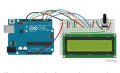
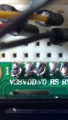
2 main methods, one with a 10k potentiometer and one using varying resistors to adjust contrast as well as backlight.

-I have followed step by step 4 different diagrams multiple times each to ensure correct wire placement.
-Double checked code
-Used different Data pins on my Arduino
-Pot started smoking after about 1min of adjusting backlight, researched this and seems that the lcd drawing to drawing to much power.

What I need help with:

I would like to know what your suggestions would be as to what to troubleshoot next. Also would love any suggestions as to what projects to do next or any great learning material you would recommend to a newbie. Attached are pictures of the two main methods Ive attempted. Thanks again!
 

Attachments

blocco a spirale

Joined Jun 18, 2008
1,546
Try connecting LEDs via 220R to 1k resistors to the control and data lines, and then slow the code right down. Observe the LEDs and confirm whether everything appears to operate as you expect.

I wouldn't bother with the back-light at this stage but contrast adjustment is essential.
 

jpanhalt

Joined Jan 18, 2008
11,087
It looks like you are using 4-bit mode. I suspect the LCD is not being correctly initialized. Posting your code and pinout from the MCU that is attached to the LCD might help.

John
 

dannyf

Joined Sep 13, 2015
2,197
-Characters will not display not an iota of color even
make sure the power connections are correct, or contrast is set up right.

Those displays will show 1 full bar if it is power up correctly and contrast is correct, even if the data sequence isn't.

So your problem is either powering or contrast. fix that first and then go to the code.
 

Thread Starter

Sir_Drizzt

Joined Nov 19, 2016
4
I am using 4 bit mode. As far as code super simple.

#include <LiquidCrystal.h>

LiquidCrystal lcd(12, 11, 5, 4, 3, 2);

void setup() {
lcd.begin(16, 2);
lcd.print("hello, world!");
}

void loop() {

}

Thanks dannyf, when connected and resistance changed between VSS and VO pin on the LCD which to my knowledge is what controls contrast, the entire screen will either dim or brighten depending on the value. I am not quite sure what you mean by a powering issue besides just recheck the wires. Here is one of the diagrams i followed. All seem generally the same just using different resistors.

Jpan- Attached is one of the diagrams ive used and is the pinouts from the MCU i am using.

Blocco- I am sorry not quite sure i understand what your suggestion is. Are you suggesting adding resistance to each of the 4 data lines i am using?
Thanks again everyone, much appreciated!
 

Attachments

dannyf

Joined Sep 13, 2015
2,197
resistance changed between VSS and VO pin on the LCD which to my knowledge is what controls contrast
you probably want to re-read the lcd datasheet - that understanding is incorrect for sure. The contrast pin needs to be sufficiently negative vs. the Vcc pin.
 

blocco a spirale

Joined Jun 18, 2008
1,546
[QUOTE="

Blocco- I am sorry not quite sure i understand what your suggestion is. Are you suggesting adding resistance to each of the 4 data lines i am using?
[/QUOTE]

I am suggesting adding LEDs (with series resistors) to the LCD data and control lines so that, if you slow the code down by adding or extending delays, you can see what is going on. By doing this you should be able to determine exactly what the problem is.

Alternatively, write a bit of test code to toggle the control an data lines so that you can check everything is mapped as intended.
 

Thread Starter

Sir_Drizzt

Joined Nov 19, 2016
4
will do danny thanks this is all still extremely new! Also looked up more about initialization seems on first boot the lcd starts in 8 bit so figuring out how to change that is also something i need to do thanks for that jpan! Sounds like a solid plan Blocco thank you! I need to finish these essays first so i can get back to this project, it is much more enjoyable! Thanks everyone!
 

jpanhalt

Joined Jan 18, 2008
11,087
There are three configurations I have come across for the Vo pin:

1) A pot is connected between VCC and VSS. The wiper is connected to Vo -- very common
2) A pot is connected between VCC and VEE (a negative voltage). The wiper is connected to Vo -- much less common than #1.
3) The pin is left not connected (more recent devices with Hitachi "compatible" controllers)

Check you datasheet and connect as shown. For the pot, 5K to 10L is common. BTW, you can use the method deacribed in #2 to run a lot of 5V displays at 3.3V.

John
 

dannyf

Joined Sep 13, 2015
2,197
I think you are on the wrong track.

An amazing feature of those LCDs is that if they are NOT correctly initialized, they display a black bar on the first line of the LCD.

Two possibilities for no display on those LCDs:

1) incorrect power / contrast;
2) incorrect code.

You have to get both right. One way to do it is to get the power / contrast right first and then work on the code.

To do that, pull one of the LCD connections, like a data line or the control lines (like EN), and see if you get the black bar on the lcd, as the lcd will never be correctly initialized. So you can focus on getting that one line of bars displayed on the lcd correctly.

For that to work, you will need to make sure that 1) the wiring works; 2) the contrast pin gets the correct voltage vs. the Vcc pin: it needs to be 3.5 - 4.2v (typical) below the Vcc line. That means about 1v vs. ground if the lcd is 5v powered and -1.0v if the lcd is 3.3v powered.

Again, you should read the datasheet of your specific lcd for sure as those numbers do vary.

Without affirming that the power and contrast works, there is no point in working on the code.
 

jpanhalt

Joined Jan 18, 2008
11,087
I thought I would update my comment in Post#9. In the past month, I have gotten 3 new character displays - two, 2X16 and one 4X16. None of them use a contrast control on Vo. In fact, the pin can be left open. All were for 3V3 supply and logic (work to 3V0 or lower).

One is a NHD purchased in the US. Its dimensioned diagram shows Vo, but the textural datasheet shows:
upload_2016-11-22_14-40-44.png

I believe its controller is a Hitachi compatible, ST7066U.

The displays I got directly from China use the SPLC7180 controller. The datasheet shows Vo, and on one, I connected the usual pot to adjust contrast. There was no change throughout the range of the pot, and one could not get the blackened boxes. Display looked to have perfect contrast. I removed the pot and left pin 3 open. No change in display, and it looked great. I have not tested the other one, but it has same controller.

I suspect displays are transitioning from the ubiquitous Hitachi controller(s) to a newer generation. At least it seems that way for the low-voltage displays. I have not gotten a 5V display in at least 2 years, so this comment may not apply to them.

John
 

Thread Starter

Sir_Drizzt

Joined Nov 19, 2016
4
Thanks for the help everyone, each of you lead me down paths to more knowledge. The problem however lied in my soldering techniques or lack there of haha. It was my first time and pins 2 and 3 were connected hence my characters would not display. Thankfully I was able to clean my board up and all works well now! Below is a before clean up and after with my board finally working. Thanks again!
 

Attachments

Top