 Facebook
 Google
 GitHub
 Linkedin
I'm using the Adafruit Metro M4 (Arduino compatible) microcontroller to build a MP3 player. I'm using the following components:
Adafruit Metro M4 feat. Microchip ATSAMD51
Adafruit VS1053 MP3/AAC/Ogg/MIDI/WAV Codec Breakout
SparkFun 16 Output I/O Expander Breakout - SX1509
I2C Encoder V2
SSD1322 OLED Display
I'm an experienced programmer, but a beginner in electronics/ciruit design. I've put everything together with breadboards and wires and it's working correctly, but now I'm trying to create 2 PCBs and I'm looking for advice based on my design. I've never created PCBs before, so I afraid that I might be missing some considerations that I need to account for.
I'm creating two PCBs: one for the microcontroller and mp3 breakout board that will sit horizontally in my case; the other for the buttons, rotary encoders, and display that will sit vertically for the face of my case.
Board #1: Microcontroller + Mp3 Breakout Board
The first PCB will be a shield for the Adafruit Metro M4. The Adafruit VS1053 will be soldered to this shield and there will be headers to connect wires from the other PCB for the inputs and display. Below is my schematic and PCB design. The PCB is almost entirely used to replace wires, connecting pins on the Metro M4 to the VS1053 and headers that connect to the second PCB. I'm also running lines to additional headers for unused pins to that I can add features in the future.


The red lines are on the top of the 2-layer PCB and the blue lines are on the bottom. So my big questions are:
1) Is there anything here that would lead to poor audio quality?
2) When connecting a shield to a microcontroller, do I need to add any components (such as resistors) that are not needed when using wires and a breadboard?
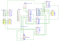
Board #2: Buttons, Rotary Encoders, and Display
The second PCB will have the buttons, rotary encoders, and display. I'm using the IO Expander because I plan to have more buttons and add other features to the microcontroller (such as FM radio, etc) that will exhaust my available pins. Also, the IO Expander does a nice job of debouncing and has a few other features that might come in handy later on. I'm using I2C Rotary Encoders so that I can continue to save on pins, but also because it does a nice job of handling double press, long press, debouncing, etc. This board will have 2 headers that lead to PBC #1: one for the display, and one for the I2C components. I could combine those but I wanted to keep them separate in case I move the display to a new location.


Is there anything wrong with this circuit?
Power
I'll be supplying 9V to the DC jack on the Metro M4.
PCB Details
2 layers, 1.6 mm thick. HASL finish. 1oz copper weight. Material type: FR4-Standard Tg 130-140C. Prototype production.
Thanks for taking a look!
Adafruit Metro M4 feat. Microchip ATSAMD51
Adafruit VS1053 MP3/AAC/Ogg/MIDI/WAV Codec Breakout
SparkFun 16 Output I/O Expander Breakout - SX1509
I2C Encoder V2
SSD1322 OLED Display
I'm an experienced programmer, but a beginner in electronics/ciruit design. I've put everything together with breadboards and wires and it's working correctly, but now I'm trying to create 2 PCBs and I'm looking for advice based on my design. I've never created PCBs before, so I afraid that I might be missing some considerations that I need to account for.
I'm creating two PCBs: one for the microcontroller and mp3 breakout board that will sit horizontally in my case; the other for the buttons, rotary encoders, and display that will sit vertically for the face of my case.
Board #1: Microcontroller + Mp3 Breakout Board
The first PCB will be a shield for the Adafruit Metro M4. The Adafruit VS1053 will be soldered to this shield and there will be headers to connect wires from the other PCB for the inputs and display. Below is my schematic and PCB design. The PCB is almost entirely used to replace wires, connecting pins on the Metro M4 to the VS1053 and headers that connect to the second PCB. I'm also running lines to additional headers for unused pins to that I can add features in the future.
The red lines are on the top of the 2-layer PCB and the blue lines are on the bottom. So my big questions are:
1) Is there anything here that would lead to poor audio quality?
2) When connecting a shield to a microcontroller, do I need to add any components (such as resistors) that are not needed when using wires and a breadboard?
Board #2: Buttons, Rotary Encoders, and Display
The second PCB will have the buttons, rotary encoders, and display. I'm using the IO Expander because I plan to have more buttons and add other features to the microcontroller (such as FM radio, etc) that will exhaust my available pins. Also, the IO Expander does a nice job of debouncing and has a few other features that might come in handy later on. I'm using I2C Rotary Encoders so that I can continue to save on pins, but also because it does a nice job of handling double press, long press, debouncing, etc. This board will have 2 headers that lead to PBC #1: one for the display, and one for the I2C components. I could combine those but I wanted to keep them separate in case I move the display to a new location.
Is there anything wrong with this circuit?
Power
I'll be supplying 9V to the DC jack on the Metro M4.
PCB Details
2 layers, 1.6 mm thick. HASL finish. 1oz copper weight. Material type: FR4-Standard Tg 130-140C. Prototype production.
Thanks for taking a look!
Attachments
-
 47.9 KB Views: 1


