Reading Filtered audio signal with arduino

Thread Starter

Yeye

Joined Nov 12, 2019
47
Hey guys, i want to make my WS2811 Led strip reactive to Bass of the music i am listening to.
The WS2811 strip is controlled by my arduino Nano. The arduino cannot read negative voltages.
I came up to 2 possible methods:
1. Using one of those tiny Microphones

2. Reading the Signal coming out of the Aux jack of my pc.

The 1st method is not really accurate because of resonances in my Room, which is why i chose the 2nd method.

There, i was offered a popular method - The MSGEQ7 IC, which is great, but also REALLY hard to get, since there are lots of fakes.
Because of that, i had to start tinkering to be able to Read the audio signal.
To achieve what i want, i need to apply a DC offset at half the arduinos voltage Reading Range ( it can read 0V-5V, so DC offset = 2.5V), and additionally Filter the signal to only get Bass.
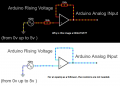
I came up with this circuit:
Screenshot (55).png
first we got a coupling capacitor, which combined with the 11k resistor builds a fixed highpass Filter. After that, 2.5V of the arduino are being added as DC offset. Then, the signal gets filtered with the RC configuration, to only get the Bass frequencies.
In theory, this should work, but practically, the arduino reads peak to peak voltages of around 200mV, which is way too low, since the signal input features peak to peak Voltages of ~3V. The RC filters lower the Signal by -6db ( ~ 50% ), so the Arduino SHOULD measure peak to peak of 1.5V, which it does not.
The code definitely is not the problem, since it only is the analogRead function and that value lowered by 512 ( the DC offset being subtracted ).

Any thoughts?

greetings from Germany
 

Veracohr

Joined Jan 3, 2011
772
The 11k resistance isn't part of the high pass. The 100uF capacitor and the two 10k resistors form the high pass.

You may need to buffer the audio before the arduino. I don't know why the level would drop so low unless the audio output from your PC has unusually high output impedance.
 

Audioguru again

Joined Oct 21, 2019
6,688
Audio usually has symmetrical positive and negative peaks so simply rectify the input signal so that the output is positive DC voltages. An active rectifier can be made with an opamp so that there is no rectifier diode voltage drop.

The LM3915 (obsolete now) ten steps of audio levels or MSGEQ7 ignore the input negative peaks and show only the positive peaks, and they are so simple that a microcontroller is not even needed.
 

Thread Starter

Yeye

Joined Nov 12, 2019
47
I originally wanted to do just that. ( Ideal Diode Circuit / Precision Half Bridge ) The Problem is just, that my opamp circuits somehow do not work as it seems. I tried building the SIMPLEST circuits you could imagine ( Voltage Follower ) with an input signal of my arduino ( The signal is DC, just a rising DC voltage over time ), then my arduino reads out the Voltage at the Output.
Screenshot (56).png
It is just as simple as that. The opamp i am using is a TL072CP . I tried building this circuit without those 2 Resistors and it also did not work. Since the supply voltage difference has to be at least 10v, i powered everything with my 12v switch mode power supply.
The Switch mode PSU is connected to Ground and Ground is connected to Vcc-, while +12v is connected to Vcc+.
Ground is connected to the Ground of Arduino, so everything is properly Grounded.
The circuit is just as simple as that, but somehow my Arduino permanently gives me a Value of 1023, which is the Maximum, aka 5v or more. What am i doing wrong?
If i got this problem fixed, the rest should be a walk in the park.

Thank you in advance
Greetings from germany

By the way: The 2nd opamp which is integrated in that IC is not connected anywhere, it just sticks in the Breadboard.
 

ericgibbs

Joined Jan 29, 2010
18,841
hi Yeye,
That circuit has missing components, it will give a fixed high output level.

E
Update:
Don't forget that the audio signal will be swinging above and below 0V.

Look at this PDF for a precision rectifier circuit.
 

Attachments

BobTPH

Joined Jun 5, 2013
8,941
TL072 is not a single supply op amp. With V- at ground it cannot output less than about 2V.

You need either a single supply op amp or a dual supply to get outputs near ground.

Bob
 

Audioguru again

Joined Oct 21, 2019
6,688
in addition to the output problem, the Inputs of the TL072 also have a problem. If they are within about 5V from the negative supply which is 0V in your circuit, then the output suddenly goes as high as it can.

Your negative Falstaff image looks awful.

An opamp as a buffer does not need the resistors you used.
 

Attachments

Thread Starter

Yeye

Joined Nov 12, 2019
47
First of all:
Thank you for telling me that. I already thought the supply is the reason why it does not work.
The resistors are there to minimize the influence of wirs resistence which could make the opamp amplify the Signal a bit.
I do not have any other opamps at home... I habe to go get some before i can continue with the opamp Method.

I still dont understand why my First circuit doesnt work... Again: if you have any ideas, just answer please

Thank you
 

Thread Starter

Yeye

Joined Nov 12, 2019
47
What does its Parameter
"Supply Voltage(Single) 7V ~ 36V, ±3.5V ~ 18V"
Mean? What is it for, if it does not work. I mean if it would work without bring able to go down to 0v, i would understand it, since it is not a rail to rail opamp. But it doesnt work and just pulls the output high. Why is that Parameter given then?
 

Audioguru again

Joined Oct 21, 2019
6,688
The datasheet recommends that power supply for a TL072 can be +10V to +30V or it can be +/-5V to +/-15V.
The datasheet also tells you that the recommended common mode range is 4V more positive than the negative supply (like I said) up to the positive supply.

I told you that since you do not have a negative part of the supply then if an input is within about 4V from the negative supply (your negative supply is 0V) then the output goes as high as it can. Without the negative supply then the inputs must be no less than about +4V.

Your input is at 0VDC and the negative supply is also at 0VDC so the output goes high.
 
If the resistor in the low pass filter is really 10 ohms (as marked), then I think that's your problem. That's the load your computer will effectively be driving -- the 100uF low-pass filter capacitor will appear as a very low impedance for most audio frequencies (that's why this circuit is a low-pass filter). Your computer can't drive a 10 ohm load -- this is way too low.

I suggest you use a much larger resistor (10k or larger) and then scale the capacitor down by the same factor (e.g. R=10k, C= 0.1uF). This will fix the computer loading problem while maintaining the filter cutoff frequency. Of course this assumes the input load of the Arduino's A/D is much higher than 10k (you'd better check that). If it's not, you'll need a buffer between the low-pass filter and the A/D input.
 

Thread Starter

Yeye

Joined Nov 12, 2019
47
Yes, i did firstly see that as a problem too, but since i had not a big selection of different capacitors, i just chose one of my lowest ones ( 100uF ) and then calculated the resistor. After that, i did not think about changing anything, since i always thought the main Problems are somewhere else. It seems a pc line out can only deliver around 3 mA, which means (as you said) this probably is the Problem. Thank you for telling me, i would not have checked this value anywhere in the near future without this hint. :_D

I will try the circuit again
 

Thread Starter

Yeye

Joined Nov 12, 2019
47
FINALLY! It makes sense now, it seems the PC lowers the volume as far as it needs, to stay below the current limit of around 3 mA.
The new circuit is easy as hell and works just fine, it looks like that:
Screenshot (58).png


Thanks to all of you, have a nice day
 
Top