If you are really worried about protection for the Arduino input, use an optoisolator.
That way, there is no electrical connection between the 12V and the Arduino.
Almost all the industrial control equipment we have designed use this.
Here is a rough circuit.
A as an input switch with B shorted for current sourcing (PNP sensor), and B as the input with A shorted with current sinking (NPN sensor).
Arduino input with active pullups used.
An alarm system,
as in a house / office one
in my experience tends to involve long wires,
In my experience of these
they pick up all sorts of horrible common mode noise
If you connection is anything apart form all in the same box,
As others have said
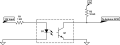
Id strongly suggest that you use an opto isolated input
and do not have common "ground"
You could use a Opto 6N138 for full isolation like this...
Note that this particular circuit open switch -> high output, which is probably what you want for a security system (Just in case someone comes along with some cutters...)
Also note that I've seen some *very* smart security circuits spoken about on AAC, that overcome lots of different ways people typically hack a security systems
An alarm system,
as in a house / office one
in my experience tends to involve long wires,
In my experience of these
they pick up all sorts of horrible common mode noise
If you connection is anything apart form all in the same box,
As others have said
Id strongly suggest that you use an opto isolated input
and do not have common "ground"
Ok it looks like I have to tell more about what I am doing.
I am doing an add on for a home alarm system.
I bring power and signal with the same cable from the central unit to the Arduino Circuit. Basically I have an AI camera connected to the central unit that act as a sensor and I want to add an Arduino circuit controlled speaker that say something before the alarm goes off. Can I adopt with the solution in the attached image?
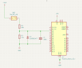
I've completed the circuit and it looks like it works in real life.
For this version of the circuit I've opted for a voltage divide insted of an opto (I will try that solution too).
Do you spot any major flaw in the design?
When the speaker is working the current draw doesn't exceed 0.2A and the speaker is supposed to work for several minutes just when the alarm goes off.
Thanks
p.s. I've used a trimmer in the voltage divider because I deal with alarm systems that give both 12V and 15V signal and power to my board.
 Facebook
 Google
 GitHub
 Linkedin