Arduino for digital potentiometer

Thread Starter

Lejeep

Joined Feb 20, 2025
22
Hello to all the community,
First post on this forum.

Knowledge background;
I am a retired civil eng with basic knowledge of electronic. With much guidance, my biggest project was troubleshooting/repair my venerable Sansui AU20000 integrated amplifier. I also learned + repaired a smps power converter. This is about the extent of my knowledge in electronic.

Project at hand;
I am "cloning" my Bose 901 equalizer from scratch.
The controls consist of just two dual gang slide potentiometers. One for bass(left+right channel)and one for treble(left+right channel).
I would like to substitute those slides with two push buttons and digital pots and five led's for each buttons with possibly 10 increments.(two increments per led)
I think I can use an Arduino to control the digipots.

1st question;
Is there an easier way to do this with my limited knowledge?
2nd question;
Would I be able to simulate a center tap digipot?
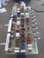
Here is part of the right channel.
You can see that R10R is a standard three pin pot, but R12R has a center tap also.

1735601074821.png

I hope the picture is clear enough and thank you in advance for taking your time.
Daniel aka Lejeep
 

KeithWalker

Joined Jul 10, 2017
3,603
To replace a center tapped pot, you could use two digital pots connected in series. An Arduino could be configured to make it work correctly.
 

Thread Starter

Lejeep

Joined Feb 20, 2025
22
Do you have a particular digipot in mind?
Thanks for the quick reply.
The answer would be no.
When my search for new center tap pots revealed nothing available, I came upon the Arduino idea suggested in another forum.
I just went so far as to confirm such an IC was available through reputable suppliers.
 

Thread Starter

Lejeep

Joined Feb 20, 2025
22
They can be tricky to use in circuits not specifically designed for them.

https://circuitcellar.com/research-design-hub/using-digital-potentiometers/

DIGITAL POTENTIOMETER LIMITATIONS
As with most design decisions, digital potentiometers also have some drawbacks.
Also thanks for replying so quickly.
I had read on the limitations about digipots before posting here.
My understanding is that voltage and current must be controlled so as not to "fry" everything.
Applying these limitations, looking at the schematic I posted previously, can you tell me if my circuit can be used with digipots?
 

Thread Starter

Lejeep

Joined Feb 20, 2025
22
To replace a center tapped pot, you could use two digital pots connected in series. An Arduino could be configured to make it work correctly.
Now this is interesting. Being just a newbi in this field, I kind of figured there were no such things as center tap digipots.
I thought it was more a matter of programming the Arduino that would simulate the center tap response along with the normal "linear" response.
Would that be feasible or do I need two in series like you suggested?
 

panic mode

Joined Oct 10, 2011
4,867
are potentiometer terminals always guaranteed to be between 0V and 5V? that would be one of limitations (assuming digital potentiometer is powered by 5V). it looks like TP22 is GND or 0V. but also several other test points sport label <=0.05VDC. to me that is not very reassuring since -15V is also <=0.05V.
 

crutschow

Joined Mar 14, 2008
38,325
thought it was more a matter of programming the Arduino that would simulate the center tap response along with the normal "linear" response.
Would that be feasible or do I need two in series like you suggested?
All the Arduino can do is change the wiper position on the pot, it can't "simulate" the tap.
To do the tap, you will indeed need two pots.
 

schmitt trigger

Joined Jul 12, 2010
2,027
Do you have a scope and signal generator available?
If so, apply the maximum sinewave input (prior to clipping) and check the peak to peak voltage at the digipot’s input terminal, as measured to ground.
Per the attached photo, it must not exceed +/-2.5Vp_p.
This is the main limitation discussed above!
BTW, the AD5235 is a dual 25k, 1024 taps device.
IMG_1049.jpeg
 

nsaspook

Joined Aug 27, 2009
16,252
Also thanks for replying so quickly.
I had read on the limitations about digipots before posting here.
My understanding is that voltage and current must be controlled so as not to "fry" everything.
Applying these limitations, looking at the schematic I posted previously, can you tell me if my circuit can be used with digipots?
https://www.analog.com/en/resources/app-notes/an-1121.html
Likely will work (with changes to the circuit power layout) if the AC audio signals are in the range of the Vdd and Vss IRT GND/COMMON. The common way to solve this is with bipolar supplies +- for Vdd and Vss,
https://www.analog.com/media/en/technical-documentation/data-sheets/ad7376.pdf
+30 V/±15 V Operation 128-Position Digital Potentiometer

"VDD and VSS power supplies define the boundary conditions for proper 3-terminal digital potentiometer operation. Applied signals present on Terminals A, B, and W that are more positive than VDD or more negative than VSS will be clamped"

There is also 'zipper' noise when quickly changing resistance because of the stepped nature of the resistance change instead of smooth and continuous with a mechanical pot.
https://www.analog.com/en/resources/app-notes/an-1291.html
A: A digital potentiometer is not an exact replacement for a mechanical potentiometer. VA and VB must not be greater than VDD or less than VSS (or GND if the device does not have a VSS pin). For example, if the desired VA and VB are +2 V and −2 V, respectively, VDD must be less than, or equal to, +2 V, and VSS must be greater than, or equal to, −2 V.

See the AN-1121 Application Note, Replacing Mechanical Potentiometers with Digital Potentiometers, for more information on this topic.
Q: If I use the digital potentiometer in audio volume control, will I experience zipper noise?

A: There is noticeable zipper noise; however, a logarithmic audio volume control circuit with glitch reduction (developed by Analog Devices using the AD5292 digital potentiometer) is available (see Figure 8). See the AN-1209 Application Note, Logarithmic Audio Volume Control with Glitch Reduction Using the AD5292 Digital Potentiometer for more information.
 

Thread Starter

Lejeep

Joined Feb 20, 2025
22
are potentiometer terminals always guaranteed to be between 0V and 5V? that would be one of limitations (assuming digital potentiometer is powered by 5V). it looks like TP22 is GND or 0V. but also several other test points sport label <=0.05VDC. to me that is not very reassuring since -15V is also <=0.05V.
I touched the "like" button by mistake, sorry.
I recently refurbished my working original Bose equalizer before this project came to mind.
I tested most TP's before closing the box and if memory serves me right, they all tested above 0VDC like what is labeled.
Because I cropped the schematic, you don't see it, but the IC's themselves are powered at pin 4+8 with "-V and +V" which are -15VDC and +15VDC respectively.

Was this just a warning on your part or did you have some course of action to suggest?
Thanks for helping out!
 

Thread Starter

Lejeep

Joined Feb 20, 2025
22
All the Arduino can do is change the wiper position on the pot, it can't "simulate" the tap.
To do the tap, you will indeed need two pots.
Got it thanks.

My limited knowledge tells me the signal going to the original slides R10R + R12R is AC. This incoming signal comes from "tape out" of the amp/preamp. I think it it called line signal and is kind of small.
Also, the IC's themselves are powered by "-V and +V" which are -15 and +15VDC respectively.
With this in mind(if I'm not totally out in left field), could I use a pair of digipots with the Arduino.
Please correct me if I am wrong.
Just trying to understand.
 

nsaspook

Joined Aug 27, 2009
16,252
I touched the "like" button by mistake, sorry.
I recently refurbished my working original Bose equalizer before this project came to mind.
I tested most TP's before closing the box and if memory serves me right, they all tested above 0VDC like what is labeled.
Because I cropped the schematic, you don't see it, but the IC's themselves are powered at pin 4+8 with "-V and +V" which are -15VDC and +15VDC respectively.

Was this just a warning on your part or did you have some course of action to suggest?
Thanks for helping out!
My 2c. Personally for me, it's not worth the effort IMO. How often do you change tonal setting? The digital electronics will likely bleed noise into the audio unless the power bus and signal lines are carefully isolated (from conducted ground noise) from the analog side.
 

Thread Starter

Lejeep

Joined Feb 20, 2025
22
Do you have a scope and signal generator available?
If so, apply the maximum sinewave input (prior to clipping) and check the peak to peak voltage at the digipot’s input terminal, as measured to ground.
Per the attached photo, it must not exceed +/-2.5Vp_p.
This is the main limitation discussed above!
BTW, the AD5235 is a dual 25k, 1024 taps device.
View attachment 342927
Thanks for this precision.
A scope and sig gen are out of my realm for the moment. Really just starting with humble dmm.
However, I just mentioned to "crutschow" the signal coming in is from "tape out" of the amp/preamp.
I would believe it is "amplified" by opamp "U301" and R307+R307 before reaching pots R10R+R12R.
That being said, do you believe it satisfies the necessary conditions to implement such digipots?
Could I measure voltages with my dmm somewhere instead?
Also thanks for mentioning the AD2535.
 

Thread Starter

Lejeep

Joined Feb 20, 2025
22
https://www.analog.com/en/resources/app-notes/an-1121.html
Likely will work (with changes to the circuit power layout) if the AC audio signals are in the range of the Vdd and Vss IRT GND/COMMON. The common way to solve this is with bipolar supplies +- for Vdd and Vss,
This is encouraging.
I believe the first link you posted is just to describe the operational differences between mech and digipots.
On the schematic(first post), you can see -V and +V going to IC's U301 and U302. You cannot see it but these are -15 and +15VDC regulated coming from the bridge rectifier and a 30VDC zeiner diode. Could these also supply Vdd and Vss.
Keep in mind I am just a newbi in electronic.

https://www.analog.com/media/en/technical-documentation/data-sheets/ad7376.pdf
+30 V/±15 V Operation 128-Position Digital Potentiometer

"VDD and VSS power supplies define the boundary conditions for proper 3-terminal digital potentiometer operation. Applied signals present on Terminals A, B, and W that are more positive than VDD or more negative than VSS will be clamped"

There is also 'zipper' noise when quickly changing resistance because of the stepped nature of the resistance change instead of smooth and continuous with a mechanical pot.
https://www.analog.com/en/resources/app-notes/an-1291.html
I have not read (yet) the entire article you linked, but in regards to "zipper" noise, if I got it right, the author is talking about a volume control being rotated rapidly.
In my case, the incrementation would be done in a "sequential" fashion. Pushing the button would yield one increment at a time only.
Do you think there would be a "zipper" effect in that configuration?
Thank you for all your expertise.
 

nsaspook

Joined Aug 27, 2009
16,252
This is encouraging.
I believe the first link you posted is just to describe the operational differences between mech and digipots.
On the schematic(first post), you can see -V and +V going to IC's U301 and U302. You cannot see it but these are -15 and +15VDC regulated coming from the bridge rectifier and a 30VDC zeiner diode. Could these also supply Vdd and Vss.
Keep in mind I am just a newbi in electronic.


I have not read (yet) the entire article you linked, but in regards to "zipper" noise, if I got it right, the author is talking about a volume control being rotated rapidly.
In my case, the incrementation would be done in a "sequential" fashion. Pushing the button would yield one increment at a time only.
Do you think there would be a "zipper" effect in that configuration?
Thank you for all your expertise.
The circuit opamp supplies should work for that digipot I linked to but it only comes in three values 10k, 50k and 100k.
https://www.mouser.com/c/semiconductors/digital-potentiometer-ics/?series=AD7376

That means the filter component capacitors will need to be changed to have close to the same response.

One increment at a time only would be a bad user interface. I would assume the reason for digital control is to have pre-sets and much the equivalent user interface to turning a mechanical control, where you could go slow or fast with adjustments.
 

Thread Starter

Lejeep

Joined Feb 20, 2025
22
My 2c. Personally for me, it's not worth the effort IMO. How often do you change tonal setting? The digital electronics will likely bleed noise into the audio unless the power bus and signal lines are carefully isolated (from conducted ground noise) from the analog side.
This equalizer is essential in order to drive my Bose901's, otherwise they sound flat.

My approach is twofold.
I would first "clone" the original eq with mechanical slide pots but make a provision on the board underneath the slides(or wherever there is room) for the digipots.
Once tested, I would remove the original slides and add the Arduino on a second level over the existing board.
However, noise is not something I had considered. Could this be a game stopper or can it be addressed by a newbi like me?
Here are both sides of the original board if that can help.
20250201_104816_HDR.jpg

20241202_130718_HDR.jpg
 

Attachments

Top