Facebook
 Google
 GitHub
 Linkedin
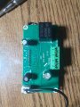
With 100 Ohms resistor, output is 10.64VSeems it needs at least 12mA load to regulate.. According to the datasheet it should be able to output 500mA at 12.3v. Have you any smaller value resistors, in the 100-500ohm range, to put in parallel make around 80 - 100 ohms, so we can prove the chip is actually regulating properly...
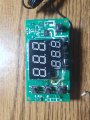
Anyone knows what this IC is?
- Thread starter FlllP
- Start date
-
- Tags
- fix heater control help tuya