Anyone knows what this IC is?

Thread Starter

FlllP

Joined Jul 19, 2025
108
Do you have an LCR meter to measure inductance? The only other reason for the output being wrong, assuming the chip isn't faulty, is a wrong inductor value - maybe it has an internal short.
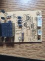
So, the green inductor should be 1000UH, I get reading for it 966.7uH and 5.5ohms

The black one should be 1.6MH, I get reading 1.6mH and 1.6ohms
 

Thread Starter

FlllP

Joined Jul 19, 2025
108
I have replaced the green inductor, and the issue still persists... At this point, I will desolder everything, and test each component individually
 

Thread Starter

FlllP

Joined Jul 19, 2025
108
okay, I tested these components individually with Fnirsi LCR-P1
ComponentTested with LCR-P1
3x 104106, 95,101
Inductor 1000UHVal:5.6Ohm L:952.5uH
Inductor 1.6MHVal: 1.7Ohm L:1.6mH
Cap 4.7UF/400VVloss:0.5% esr: 2.47Ohm Cap 4.1uF
Cap 4.7UF/400VVloss:0.4% esr: 2.53Ohm Cap 4.2uF
Cap 470UF/25VVloss:1.6% esr: 0.11Ohm Cap 459uF
Cap 10UF/50VVloss:0.3% esr: 1.48Ohm Cap 10.0uF
Cap 223J20nF
FR107Vf:637mV Ir:5.7nA Cap: 10pF
BYC26Vf:572mV Ir:5.1nA Cap: 10pF
Cap 1.6MH82nF
10K471220pF
 

Blisspp

Joined Feb 26, 2026
1
Hi, when testing SMPSs make sure there is a load. Is it possible that the power supply board is not being loaded properly and the failure is elsewhere(?) ...just an idea!
 

Irving

Joined Jan 30, 2016
5,145
Also, when I attach the 2k resistor at the power for control board, voltage gets static at 15V..
That's interesting... it should regulate all the way down to near zero current... maybe it needs a minimum load current to regulate. There's nothing in the datasheet to indicate that, though it does show a 2k bleed resistor on the example circuit.. Try a 1k2 1/2W resistor.
 

Thread Starter

FlllP

Joined Jul 19, 2025
108
That's interesting... it should regulate all the way down to near zero current... maybe it needs a minimum load current to regulate. There's nothing in the datasheet to indicate that, though it does show a 2k bleed resistor on the example circuit.. Try a 1k2 1/2W resistor.
This outputs 15V... instead of 4.7uF/25V i put 10uF/50V because I dont have 4.7/25V, and instead capacitor 333, i put 2A223J green capacitor
 

Attachments

Irving

Joined Jan 30, 2016
5,145
This outputs 15V... instead of 4.7uF/25V i put 10uF/50V because I dont have 4.7/25V, and instead capacitor 333, i put 2A223J green capacitor
Not seen a circuit built like that for many years!

But it should be outputting 12V or I am missing something?
What value is the load resistor? What happens if you make it smaller, ie put another similar in parallel?


Latest schematic with all components now identified:

1772192532481.png
 

Irving

Joined Jan 30, 2016
5,145
Seems it needs at least 12mA load to regulate.. According to the datasheet it should be able to output 500mA at 12.3v. Have you any smaller value resistors, in the 100-500ohm range, to put in parallel make around 80 - 100 ohms, so we can prove the chip is actually regulating properly...
 

Thread Starter

FlllP

Joined Jul 19, 2025
108
Seems it needs at least 12mA load to regulate.. According to the datasheet it should be able to output 500mA at 12.3v. Have you any smaller value resistors, in the 100-500ohm range, to put in parallel make around 80 - 100 ohms, so we can prove the chip is actually regulating properly...
so in theory, that small electrolytic capacitor should act as a load on control board, let me replace it and test it
 
Top