another 555 problem.

Thread Starter

campeck

Joined Sep 5, 2009
194
I think I understand.
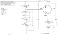
Since current is set by the load/collector resistor (right?) then once the amount of base current needed to supply the load current(Hfe ratio?) is reached no more can flow. and the only downside to increasing the Ib is heat? So that's why with small currents and LED's you just say "use a 1k ohm" because we aren't operating at the edge of device tolerances?
 

SgtWookie

Joined Jul 17, 2007
22,230
"When a transistor is saturated, Vce is minimal and an increase in base current will not lead to an appreciable corresponding increase in collector current."

But when is that point reached? I'm having trouble understanding that for some reason. Is there another way to explain it? I feel like I'm just getting more confused. Would saturation for a hfe100 transistor supplying 100ma be 1ma and up until the max power dissipation?
When you're forcing beta, you don't pay attention to the rated hFE.
You look at the saturation curve in the datasheet to figure out if the device will supply the Ic you need with a reasonably small power dissipation by a low Vce.

Then you feed the base with 1/10 of the desired collector current. In many cases, this is overkill. However, it will work in ALL cases when the transistor is functioning and within manufacturer's specifications.

I'm going to have to get back to you on the rest of this; it's late, I'm tired, and AAC goes into maintenance mode at about this time.
 

Thread Starter

campeck

Joined Sep 5, 2009
194
Cool. I pulled up the datasheet and looked at what I think was the saturation curve.
Well I look forward to learning more tomorrow!
 

SgtWookie

Joined Jul 17, 2007
22,230
Like, I'm trying to figure out the problem of the pull up resistor and I assume you mean something like this right? (see pic) But I am getting overwhelmed with what should be simple. I honestly have no idea what's going on. I will think I know, like when I read what you write. And then when I try to implement it, it all falls apart.

My one time getting through all the equations I got 590Ω.
But I think that's wrong.
I thought the diodes need to drop 1.3v so .65v a piece which is 2.2ma so 1.3/.0022 = 590
OK, pull out your datasheet for the 2N2907, and look for the "Base Cut-off Current" specification. You'll see that it's given at Vbe=0.5v. But you're not really looking for the base current, you're looking for that Vbe specification.

So if V+ is 5v, you need to get the base to at least 4.5v in order to turn off that PNP transistor.

When the output of the 555 timer is high, it measures 3.7v. So, you need 4.5v - 3.7v = 0.8v more than the 555's output voltage (minimum) in order to get the PNP transistor into cutoff.

Earlier, I suggest that you use two diodes in series with the base resistor to get the transistor to turn off. However, there wasn't enough current flowing through the diodes to drop enough voltage across them to get the transistor's base to 4.5v or higher, turning it off.

Pulling out that handy-dandy 1N4148 plot that I posted earlier, I see that in order to get a 0.4v drop across the diode, I need at least 0.02mA (20uA) current flow through it. However, not all diodes measure the same, and we want to be pretty certain that the transistor will be cut off under most conditions. Let's go with the 0.05mA (50uA) current flow, which may give around 460mV, but we'll still call it 0.4v. The two diodes in series need to drop at least 0.8v.

Now the problem is reduced to how much resistance do we need to cause 50uA to flow across Vsupply - (VfD1 + VfD2 +Vout555)?
R = (5v - (0.4v + 0.4v + 3.7v)) / 50uA
R = (5 - 4.5) / 0.00005
R = 0.5 / 0.00005
R = 10,000 Ohms.
Note that up to now, I've completely ignored the 1k base resistor. We'll subtract that 1k from the resistance requirement, leaving 9k for the pull-up resistor.

I've already built in a bit of overkill to ensure that the transistor goes into cutoff. Standard resistor values nearest 9k are 8.2k and 9.1k. For this purpose, 9.1k should be plenty close enough; it's only 1.1% higher than 9k.

Now, the 9.1k pull-up resistor will reduce the base current somewhat when the 555 output goes low; and so will the two diodes D1 and D2. You can figure out what the new base current will be, right?

Could you possibly label the current and voltages so that I can understand what's going on? I'm kinda bummed I can't understand this. I was doing so well!
OK, see the attached. The letters in the colored circles correspond to the simulated O-scope traces below. (A) is a simulated 555 timer output. (B) is the voltage on the base. (C) is the collector voltage. Note that when (A) is high, (B) is above 4.5v, which means that the transistor is in cutoff.
 

Attachments

Thread Starter

campeck

Joined Sep 5, 2009
194
Now, the 9.1k pull-up resistor will reduce the base current somewhat when the 555 output goes low; and so will the two diodes D1 and D2. You can figure out what the new base current will be, right?
I understand exactly what you did. And that's how it goes for me. I can't figure anything out even when I have all the tools to do so. But once I'm shown how, it all makes sense. I don't know if it's a lack of mathematical understanding or what. But it really frustrates me.:mad:

Now on to this second problem.
Of course I can't figure it out and I don't even know why. To find current you need to divide voltage by total resistance right? Well isn't the "resistance" of the diodes dependent on the current? So I don't even know where to begin. And yet the answer is probably simple.

What I really need help in is understanding manipulating what I know and using that to find out what I want.

Thanks for putting up with my ignorance.

Is it just 5v/10k = .5ma?
 

Thread Starter

campeck

Joined Sep 5, 2009
194
Here is my cut short attempt at just defining parameters at different points in the circuit. I can't even get past defining the current!
Could someone walk me through the method and math?
 

Attachments

Wendy

Joined Mar 24, 2008
23,797
Simple enough, assume the diodes drop .6V each. We know this is a variable, but for the most part it is close enough and works. So the resistors see the power supply minus the diode drop (5VDC - .6 -.6 = 3.8V). Figure the the voltage (3.8V) divided by total resistance (10KΩ), this will give you current (3.8V / 10KΩ = 0.38ma). From there it is simple ohm's law, figure the drop across each resistor (remember, we're treating the diodes voltage as a constant). The answer will be very close.
 

Thread Starter

campeck

Joined Sep 5, 2009
194
Ok. So the new base current is .38mA and the rest of the circuit parameters are here. Tomorrow I will draw the circuit with and without the pull-up resistor and see If I can grasp all of these concepts.

Does my work check out? There are also some other questions on the pic.
Thanks!
 

Attachments

SgtWookie

Joined Jul 17, 2007
22,230
Nope! Go fish! Bill, Bill, ... tsk tsk!

You completely left out the be junction of the 2N2907, which acts VERY similarly to ... are you ready for it? .... A DIODE!

So now you have a 9.1k resistor in parallel with a BE junction (which acts like a diode) attached to V+.
Connected to that, you have two more diodes in series with a 1k resistor tied to ground.
Like this:


Both schematics are basically equivalent.

It's really kind of important for you to get this straight in your BHG.

Here's a hint.
You know that there is a 1k resistor in series with 3 diodes. We'll just forget about the 9k resistor for the moment.
Your rails are 5v and 0v (GND)
Maximum possible current is 5v /1k = 5mA - even if all the diodes were shorted (which they aren't...)
So how much voltage will the diodes drop when there is somewhat less than 5mA current flowing through them?

Find that out, subtract the Vf, and recalculate.
 

Attachments

Last edited:

SgtWookie

Joined Jul 17, 2007
22,230
OK, your questions on the schematic:
Vce - when a transistor is saturated, Vce is generally around 0.3v or less, unless you're trying to "push" a transistor's specifications. For example, even though a 2N3904 is rated for Ic=200mA max, you really should only use that transistor at/below Ic=100mA, because otherwise Vbe increases dramatically along with power dissipation.

And yes, subtract Vce from your available load voltage.

E current: well, what do you think that the base current is? :)
When the transistor is saturated, Vce is very low, and therefore increasing Ib won't result in any appreciable increase in Ic.

Remember, we're using the transistors as saturated switches, not as linear amplifiers.

Also remember that the load has a current limiting resistor.

Do you remember what I said before about forcing beta?
 
Last edited:

Thread Starter

campeck

Joined Sep 5, 2009
194
So you could say that a transistor is like a pressure switch.
in that when you press harder on the switch with current (Ib) (not voltage) it allows more and more current through (Ic), and saturation is when you push harder than needed to supply the Ic.

So to shutoff, this transistor needs less than .5v Vbe. This is the voltage needed to overcome what is basically a diode.
Then when operating as a switch(sat) we just use 1/10th the current the Ic needs on the Base,(forcing a beta of 10) combined with a higher Vbe than .5v to forward bias the emitter/base junction.
(And if you push more than 5v on the Vbe It will break? (data sheet))
We also want to make sure the Ic needed doesn't correspond with a high Vce as this will increase power consumption and result in heat. Resulting in the Vbe needing more voltage to forward bias it.
So what happens if the base sees more than 1/10 of the Ic? What If it gets Ic?

So to get Ic I do:

Vs - LED(Vf) - Vbe(.5v?)
_________________________________ = Ic
R1(current limiting LED resistor)

Or Do I need to subtract Vce as well? why or why not?

Vs - LED(Vf) - Vbe(.5v?) - Vce
_________________________________ = Ic
R1(current limiting LED resistor)

So to get my LED limiting resistor is:
Vs-Vf(led)-Vbe
_____________ = R1
current of LED

Then Ib is 1/10th of Ic for a saturated switch so:
Ic
__ = Ib
10

So the Base resistor is:
10
__ X V at base
Ic

Since the pullup resistor is in parallel with the transistor when ON, most of the current goes through the transistor and the pullup resistor has little effect on circuit current correct?

"So how much voltage will the diodes drop when there is somewhat less than 5mA current flowing through them?"

So we can really just use guesswork like this?
I think a lot of the reason I get stuck is there are so many variables controlling variables I don't know where to start!

You know, I can't find the diode voltage drop because that depends on the current through the circuit. But the current depends on the voltage drop! So what your saying is just know that each diode will lower the circuit current so just estimate?

I will post my recalculated circuit in a bit. I also need more 9v batteries!


"E current: well, what do you think that the base current is? :)"
a tenth of it. lol ok...
 
Last edited:

SgtWookie

Joined Jul 17, 2007
22,230
So you could say that a transistor is like a pressure switch.
in that when you press harder on the switch with current (Ib) (not voltage) it allows more and more current through (Ic), and saturation is when you push harder than needed to supply the Ic.
Ahhh ... sort of.
Current = volume of electrons moving.
Voltage = electrical pressure.

So to shutoff, this transistor needs less than .5v Vbe. This is the voltage needed to overcome what is basically a diode.
When Vbe for that transistor is down to 0.5v or less, so little collector current is able to flow that the transistor is considered to be in cutoff. If Vbe is 0.5v or less, very little Ib is flowing.

Then when operating as a switch(sat) we just use 1/10th the current the Ic needs on the Base,(forcing a beta of 10) combined with a higher Vbe than .5v to forward bias the emitter/base junction.
Any appreciable Ib implies that Vbe is greater than 0.5v for that transistor.
The higher Ib is, the greater Vbe will be; but it's not a linear relationship - it's much like the diode Vf vs current plot I posted earlier.

(And if you push more than 5v on the Vbe It will break? (data sheet))
You will release the magic smoke.

We also want to make sure the Ic needed doesn't correspond with a high Vce as this will increase power consumption and result in heat.
It will result in increased power dissipation in the transistor, resulting in heat, and if too high, smoke.
Resulting in the Vbe needing more voltage to forward bias it.
No, more Ib. Although a few claim that bipolar junction transistors are controlled by voltage, conventional theory is that current flow through the base results in a greater current flow through the collector.
So what happens if the base sees more than 1/10 of the Ic? What If it gets Ic?
Well, that would be somewhat of a waste of current.
Most of the time, you can get a transistor to saturate when Ib is 1/15 or 1/20th of Ic. However, when Ib = 1/10 Ic, you're virtually guaranteed that the transistor will be in saturation. If you're making something in a manufacturing production environment, you would wind up having lots of failures and re-works if you tried to cut things too closely. Failures and re-works will rapidly eat up profits, and quickly put you in the red.
So to get Ic I do:

Vs - LED(Vf) - Vbe(.5v?)
_________________________________ = Ic
R1(current limiting LED resistor)
Nope.
Ic = (Vs - (Vf(LED) + Vce)) / Rlimit
Ic = (5v - (2.1v + 0.2v)) / 110 Ohms
Ic = (5v - 2.3v) / 110
Ic = 2.7 / 110 = 0.0245...A = 24.5mA
I'm using 0.2v for Vce(sat), which is actually quite a bit more than the datasheet indicates for that Ic. At room temperature, actual Vce when Ic is around 25mA, Vce will be about 0.06v. See the graph in ST Microelectronics' datasheet for the 2N2905/2N2907.

Or Do I need to subtract Vce as well? why or why not?
The CE junction is in the current path, so Vce needs to be subtracted from Vs. Same as Vf(LED).

Vs - LED(Vf) - Vbe(.5v?) - Vce
_________________________________ = Ic
R1(current limiting LED resistor)
Nope. The correct formula is above.

So to get my LED limiting resistor is:
Vs-Vf(led)-Vbe
_____________ = R1
current of LED
You're getting Vbe confused with Vce.
R1 >= (Vs - ( Vf(LED) + Vce)) / DesiredCurrent

Then Ib is 1/10th of Ic for a saturated switch so:
Ic
__ = Ib
10
That'll work.

So the Base resistor is:
10
__ X V at base
Ic
(Putting on campaign cover) Just BEGIN!
How on EARTH did you come up with that?

Since the pullup resistor is in parallel with the transistor when ON, most of the current goes through the transistor and the pullup resistor has little effect on circuit current correct?
It will have some effect.
Once you figure out the circuit I posted, you will get an idea of how much current is flowing through the be junction, and then you can figure out (using the 1N4148 plot) what the Vf will be, and then figure out how much current would go though the 9.1k resistor with that amount of voltage across it.

"So how much voltage will the diodes drop when there is somewhat less than 5mA current flowing through them?"

So we can really just use guesswork like this?
I think a lot of the reason I get stuck is there are so many variables controlling variables I don't know where to start!
Why don't you look at that 1N4148 plot that I keep bringing up like a broken record, and take a stab at determining what the Vf of the diodes might be, then sum up the voltage drop and re-calculate the voltage drop across the resistor to get closer to what it's actual current will be?

You know, I can't find the diode voltage drop because that depends on the current through the circuit. But the current depends on the voltage drop! So what your saying is just know that each diode will lower the circuit current so just estimate?
You could start with an approximate number to get close. Why don't you look at that 1N4148 plot that I keep bringing up like a broken record... :rolleyes:

I also need more 9v batteries!
Save yourself some money and get a wall-wart supply. If you don't have one, they are available very cheaply from places like Marlin P. Jones & Associates:
http://www.mpja.com
They sell wall warts for $2-$3, about what you'd spend for a single battery.

"E current: well, what do you think that the base current is? :)"
a tenth of it. lol ok...
Don't make me get out the pugil sticks. :eek:
 

SgtWookie

Joined Jul 17, 2007
22,230
How am I looking?
and Id being current through the Diodes. which I assumed to be around 3mA
Yep. Current through the diodes and R1 is right about 2.98mA in simulation.
However, Ib is 2.9mA and current through R2 (9.1k) is 80uA.

Take a look at Vce in the datasheet with your expected Ic.

89 Ohms is too low for R3.

Start using standard resistor values.
A table of standard resistance values is available online here:
http://www.logwell.com/tech/components/resistor_values.html
Bookmark that page.
Use the E24 (green) data columns; they are 5% tolerance values and adequate for most purposes. You can get the E48 through E192 values if absolutely necessary, but you will almost always have to order them.

If you insist on using closer tolerances for some reason, you can use resistors in series or parallel to arrive at a more precise value. Here is an online calculator for that:
http://www.qsl.net/in3otd/parallr.html
Bookmark that page.
 

Thread Starter

campeck

Joined Sep 5, 2009
194
Ahhh ... sort of.
Current = volume of electrons moving.
Voltage = electrical pressure.
I understand.

When Vbe for that transistor is down to 0.5v or less, so little collector current is able to flow that the transistor is considered to be in cutoff. If Vbe is 0.5v or less, very little Ib is flowing.
So It's not that it needs .5v to overcome the junction. it's just when there is that little voltage practically no current is flowing? So off.


any appreciable Ib implies that Vbe is greater than 0.5v for that transistor.
The higher Ib is, the greater Vbe will be; but it's not a linear relationship - it's much like the diode Vf vs current plot I posted earlier.
So like I said above. It's because there is little base current that Vbe is said to be .5v And It's not linear. Check.


You will release the magic smoke.
Don't want that.

It will result in increased power dissipation in the transistor, resulting in heat, and if too high, smoke.
k

No, more Ib. Although a few claim that bipolar junction transistors are controlled by voltage, conventional theory is that current flow through the base results in a greater current flow through the collector.
Hm. k. Current controlled.

Well, that would be somewhat of a waste of current.
Most of the time, you can get a transistor to saturate when Ib is 1/15 or 1/20th of Ic. However, when Ib = 1/10 Ic, you're virtually guaranteed that the transistor will be in saturation. If you're making something in a manufacturing production environment, you would wind up having lots of failures and re-works if you tried to cut things too closely. Failures and re-works will rapidly eat up profits, and quickly put you in the red.
Ok so just give yourself lee-way.

Nope.
Ic = (Vs - (Vf(LED) + Vce)) / Rlimit
Ic = (5v - (2.1v + 0.2v)) / 110 Ohms
Ic = (5v - 2.3v) / 110
Ic = 2.7 / 110 = 0.0245...A = 24.5mA
I'm using 0.2v for Vce(sat), which is actually quite a bit more than the datasheet indicates for that Ic. At room temperature, actual Vce when Ic is around 25mA, Vce will be about 0.06v. See the graph in ST Microelectronics' datasheet for the 2N2905/2N2907.
Ok OK. That's what I meant to write! I meant to put plus in between the Vf and Vce And I thought It was weird that you said Vbe.;)


The CE junction is in the current path, so Vce needs to be subtracted from Vs. Same as Vf(LED).
:cool:


Nope. The correct formula is above.
kool

You're getting Vbe confused with Vce.
R1 >= (Vs - ( Vf(LED) + Vce)) / DesiredCurrent
You confused me! See below;)

and yes, subtract Vbe from your available load voltage.
I guess you meant Vce!

That'll work.

(Putting on campaign cover) Just BEGIN!
How on EARTH did you come up with that?
err.....It was scrabbled on one of my notes. My bad.

RB = Vs/Ib
?
it's late.
And I'm dumb.

It will have some effect.
Once you figure out the circuit I posted, you will get an idea of how much current is flowing through the be junction, and then you can figure out (using the 1N4148 plot) what the Vf will be, and then figure out how much current would go though the 9.1k resistor with that amount of voltage across it.
yay I did it but i didn't write the .000074A I came up with! which seems to be right along those lines.
I thought since the PN junction drops .67v at 3ma voltage is the same in parallel so .67v must be across the resistor!

Why don't you look at that 1N4148 plot that I keep bringing up like a broken record, and take a stab at determining what the Vf of the diodes might be, then sum up the voltage drop and re-calculate the voltage drop across the resistor to get closer to what it's actual current will be?
See circuit.

You could start with an approximate number to get close. Why don't you look at that 1N4148 plot that I keep bringing up like a broken record... :rolleyes:
I looked!

Don't make me get out the pugil sticks. :eek:
haha! I think I need the motivation!
 
Last edited:

SgtWookie

Joined Jul 17, 2007
22,230
So It's not that it needs .5v to overcome the junction. it's just when there is that little voltage practically no current is flowing? So off.
Yep. If you look at the 1N4148 plot, you'll see that at 100uA, the Vf of the diode is below 0.5v. As the diode's Vf is dependent upon it's current flow, the Vbe is also dependent upon the current flow.

So like I said above. It's because there is little base current that Vbe is said to be .5v And It's not linear. Check.
Yep.
Ok so just give yourself lee-way.
Built-in overkill. Why use a 2x4 when a 4x12 will work just fine? :D

Ok OK. That's what I meant to write! I meant to put plus in between the Vf and Vce And I thought It was weird that you said Vbe.;)
Yeah, I wrote that when I was late and tired. Sorry for the confusion. :rolleyes:
I guess you meant Vce!
Yep; I went back and corrected it.
err.....It was scrabbled on one of my notes. My bad.
RB = Vs/Ib
?
It's more like:
Rb = (Vs-Vbe)/Ib
So, where do you get Vbe if it's dependent on Ib? That handy-dandy plot tells me that 5mA current will give about 0.7v Vf, which is plenty good enough.
So:
Rb = (Vs-0.7)/Ib
But in this case, we also have a couple of diodes in the path of current from the base to ground; you'd need to subtract their Vf as well. Fortunately, it'll be about the same Vf. So,
Ic = 25mA
Ib = Ic/10
Ib = 2.5mA
Rb = (Vs-(0.7x3)/Ib
Rb = (5-2.1)/2.5mA
Rb = 2.9/0.0025
Rb = 1160 Ohms.
1k Ohm is plenty close enough. You COULD fiddle around with using 1.1k or 1.2k resistors, which would be technically correct, and would save a bit of current. However, many hobbyists just have E6 or E12 resistors on hand, if that. We tend to "ballpark" things around these forums, as it's most important to the hobbyists on board to just get something working rather than get everything calculated down to the Nth degree. ;)

yay I did it but i didn't write the .000074A I came up with! which seems to be right along those lines.
I thought since the PN junction drops .67v at 3ma voltage is the same in parallel so .67v must be across the resistor!
Yep. Keep in mind that what you calculate out in your head, on paper, in simulations etc isn't always what you'll get when working with real components. However, if you've already done the calculations and know what voltages/currents to expect in the circuit, it shouldn't take you very long to find out where the problem(s) with the circuit lies.
 

Thread Starter

campeck

Joined Sep 5, 2009
194
Yep. If you look at the 1N4148 plot, you'll see that at 100uA, the Vf of the diode is below 0.5v. As the diode's Vf is dependent upon it's current flow, the Vbe is also dependent upon the current flow.
Gotcha. so that chart basically is a Vbe graph and i can assume Tha transistor uses the 1N4148 plot?

Yeah, I wrote that when I was late and tired. Sorry for the confusion. :rolleyes:
No problem!

It's more like:
Rb = (Vs-Vbe)/Ib
So, where do you get Vbe if it's dependent on Ib? That handy-dandy plot tells me that 5mA current will give about 0.7v Vf, which is plenty good enough.
So:
Rb = (Vs-0.7)/Ib
But in this case, we also have a couple of diodes in the path of current from the base to ground; you'd need to subtract their Vf as well. Fortunately, it'll be about the same Vf. So,
Ic = 25mA
Ib = Ic/10
Ib = 2.5mA
Rb = (Vs-(0.7x3)/Ib
Rb = (5-2.1)/2.5mA
Rb = 2.9/0.0025
Rb = 1160 Ohms.
1k Ohm is plenty close enough. You COULD fiddle around with using 1.1k or 1.2k resistors, which would be technically correct, and would save a bit of current. However, many hobbyists just have E6 or E12 resistors on hand, if that. We tend to "ballpark" things around these forums, as it's most important to the hobbyists on board to just get something working rather than get everything calculated down to the Nth degree. ;)
Rb = (Vs-Vbe)/Ib = Sweet! Thanks
I guess I just want to practice everything to the Nth degree because I feel if I understand the basics of what voltage, current, and resistance are doing what where then I will just have a better understanding.

Yep. Keep in mind that what you calculate out in your head, on paper, in simulations etc isn't always what you'll get when working with real components. However, if you've already done the calculations and know what voltages/currents to expect in the circuit, it shouldn't take you very long to find out where the problem(s) with the circuit lies.
Cool.

You have been a HUGE help Sgt! I'm sure I'll have more problems and questions in the future. Thanks to everyone again!
:cool:
 

SgtWookie

Joined Jul 17, 2007
22,230
Gotcha. so that chart basically is a Vbe graph and i can assume That transistor uses the 1N4148 plot?
Well, not exactly. :confused: ;) I just used it to save some time.

It's "close enough" to use with small silicon signal/switching transistors.

The difference between the actual transistor and the diode plot would be so small as to be of little consequence; perhaps 1/10 volt, give or take a bit.

If you were talking germanium transistors (antique) that would be another story. Germanium transistors have a far lower Vbe cutoff threshold, but they have been obsolete for a number of years.

I guess I just want to practice everything to the Nth degree because I feel if I understand the basics of what voltage, current, and resistance are doing what where then I will just have a better understanding.
Yep, it's important to get the basics down. Then you can go on to bigger and more confusing things! :confused: ;)

Now if you really want to get a pretty good background, go through the Navy NEETS materials, available online at no cost, here:
http://www.phy.davidson.edu/instrumentation/NEETS.htm

I went through a predecessor course (called AFTA, for Advanced First Term Avionics) back in the 70's, and much of the material I studied is also in the NEETS course; it's naturally been reorganized somewhat.

If you spend 5 days a week, 8 hours a day going through the material, working all the problems and doing all the labs, it'll probably take you about 7 to 8 months to go through it all.
 
Top