another 555 problem.

Thread Starter

campeck

Joined Sep 5, 2009
194
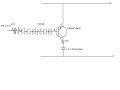
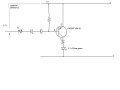
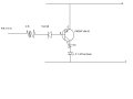
on this circuit the LED on the PNP transistor doesn't turn off when the output is high and the other LED is lit.

It just stays on and dims when the output is high.
I have a pounding headache from all this math and looking at the computer screen.
So I'll be able to give more info tomorrow. Thanks guys.
 

Attachments

Last edited:

SgtWookie

Joined Jul 17, 2007
22,230
OK, same problem - the output of the 555 timer will go down to nearly ground when low, but won't go above about Vcc-1.3v (in your case, 3.7v) when high.

A quick fix:
Put a couple of diodes in series between the base of the PNP transistor and it's current limiting resistor, anodes towards the base; in your schematic's case the 4.4k resistor.

You have rather large values (4.4k and 15k) for the resistors on the bases of the transistors. Replace them with 1k Ohm resistors.
 

Wendy

Joined Mar 24, 2008
23,429
The inability of the 555 to go rail to rail is a problem. I've been looking at it for a while, there isn't any easy answers. Here are a couple of solutions I've come up with, neither is that great.


JoeJester

Joined Apr 26, 2005
4,390
Why is the OP using the transistors in the first place? You could arrange the Limiting Resistors and the diodes to work off the 555 output directly.

Now, if this is an exercise in interfacing with transistors, belay my last.
 

Wendy

Joined Mar 24, 2008
23,429
If you've followed the several threads the OP is having a little problem with the 555 not being rail to rail. The above do this, but I don't like the parts count. The plus side is they have more current and/or voltage out. I showed them by way of illustration.

I think most of it is just learning the 555's idiosyncracies, and a primitive SPICE model.
 

JoeJester

Joined Apr 26, 2005
4,390
I understand now why Sgt said it was "the same problem". I read the other thread where the OP's original output indicators were just the LEDs and limiting resistors. So their condition changed for this thread, but the problem remained the same.

I wonder which simulation program they are using?

I agree with your analysis of the OPs difficulties.
 

Thread Starter

campeck

Joined Sep 5, 2009
194
The values on the transistor bases:

I calculated these values using the formulas I can find online which all seem to be a bit different. Can any one give me the end all formula for transistor Rb using the load current desired and the voltage supplied to the base and the hfe?

These are some of the ones I find on the internet.
RB = Vc × hFE where Vc = IC supply voltage
----------------
.........5 × Ic (in a simple circuit with one supply this is Vs)

RB = 0.2 × RL × hFE

RB = Supply Voltage / ( Maximum Current Required / Minimum HFE * 1.3 ) (I used this one)

My PNP transistor has a hfe(min) of 35 instead of 100 for the NPN

You say use 1k ohm resistors. Is this because when used as a switch as long as you don't pass the base current limit or power dissipation limit it will still work fine? Can you over-saturate?

I tried one diode with anode toward the base but it didn't work. Not sure what this would do?

And yeah, I'm just practicing with implementing transistors.

I'm trying to understand what this one you posted will do Bill?

What connects to the collectors? And won't the LED current be limited to the base current?

Sorry if these are dumb questions. I'm just trying to understand exactly what's happening. You guys have been a big help so far though! Thanks!
 
Last edited:

Thread Starter

campeck

Joined Sep 5, 2009
194
I understand now why Sgt said it was "the same problem". I read the other thread where the OP's original output indicators were just the LEDs and limiting resistors. So their condition changed for this thread, but the problem remained the same.

I wonder which simulation program they are using?

I agree with your analysis of the OPs difficulties.
No simulation program. Just lots of sticky notes! (they are covering my desk. lol)
 

Wendy

Joined Mar 24, 2008
23,429
Yes, the collect current is controlled by the base current, but this still leaves a lot of room. The 555 can source up to 0.2A, so if we design accordingly the transistors could theoritcally source/sink amps.

The big point I was making though is what is called rail to rail. Some devices, like CMOS, have it, the 555 doesn't, most op amps don't. Rail to rail is the ability to reach the power supply voltages on both sides. This is not a description of current, but of voltage. The circuits I drew will do rail to rail quite well, and could source more current too.

Most of the formula for 555's work, but a lot of them use single digit numbers (such as .7) because they are approximations. You want accuracy you add a pot to tweak the project where you want it. A 555 is very repeatable though, so if you substitute a 555 for another 555 you will likely not notice the difference. If you find values that do what you want they will repeat for other peoples projects.

To really understand the subtle differences lack of rail to rail can make read the 555 Hysteretic Oscillator. If the 555 did go to rail to rail it would be a true 50% duty cycle, indeed a CMOS 555 will approach the ideal quite closely.

I'm one of the fans for 555's around here, so I've taken it upon myself to write some articles (maybe a whole chapter) for the AAC book on them, from a practical standpoint.

Here is a little datasheet you might find handy.


Thread Starter

campeck

Joined Sep 5, 2009
194
well 6 diodes in between the base and resistors make it work.
The LED didn't dim at all...though. So it works exactly How I wanted. What did this do to the circuit?

The one drawn below has one instead of 6 diodes. can anyone also tell me the current going through the led with the configuration? because it is brighter than the one on the NPN transistor.

and Bill I will definitely be using that sheet! thanks!
do the equations change much with a diode bypassing Rb on the oscillator circuit? to achieve below 50% duty cycle.
 

Attachments

SgtWookie

Joined Jul 17, 2007
22,230
The values on the transistor bases:

I calculated these values using the formulas I can find online which all seem to be a bit different. Can any one give me the end all formula for transistor Rb using the load current desired and the voltage supplied to the base and the hfe?
It's pretty common when using a transistor as a switch to simply force a beta of 10; you can be assured that the transistor will be well-saturated that way.
3.7v/1k=3.7mA base current, allowing for up to 37mA collector current, sufficient to drive an LED or two in parallel.

These are some of the ones I find on the internet.
RB = Vc × hFE where Vc = IC supply voltage
(in a simple circuit with one supply this is Vs) 5 × Ic
RB = 0.2 × RL × hFE

RB = Supply Voltage / ( Maximum Current Required / Minimum HFE * 1.3 ) (I used this one)

My PNP transistor has a hfe(min) of 35 instead of 100 for the NPN

You say use 1k ohm resistors. Is this because when used as a switch as long as you don't pass the base current limit or power dissipation limit it will still work fine?
That's correct.
Can you over-saturate?
If you deeply saturate a transistor, it will take a long time for it to exit from saturation. This will affect high-frequency operation, but nothing to worry about at the slow speeds you are working with.

I tried one diode with anode toward the base but it didn't work. Not sure what this would do?
The diode causes a voltage drop across itself when current is passed through it.
You could use an LED instead to create a voltage drop. It may glow dimly.
 

Thread Starter

campeck

Joined Sep 5, 2009
194
It's pretty common when using a transistor as a switch to simply force a beta of 10; you can be assured that the transistor will be well-saturated that way.
3.7v/1k=3.7mA base current, allowing for up to 37mA collector current, sufficient to drive an LED or two in parallel.
Not sure what you mean by forcing beta...
So instead of calculating the load current desired and getting a Rb from that I should set an Rb and then lower the current to the led with bigger resistors? Just staying within the transistors max Ic?
which brings up this that I haven't thought Of until now. Since I calculated the Rb to give 20ma at the load do I even need LED resistors? The current is already limited by Rb correct? or does this not apply in saturation (which is what exactly?)


The diode causes a voltage drop across itself when current is passed through it.
You could use an LED instead to create a voltage drop. It may glow dimly.
well with 6 diodes I think I understand.
When pin 3 is high it outputs 3.7v and the 5v on the emitter leaves 1.3v to overcome the .7 required to flow current through the PN junction. So shouldn't one diode be enough to lower the potential difference to .6 and not allow current to flow and turn the LED on dimly?

I measured the voltage drop on the 6 diodes and it's .66v with the output high (LED off) and 2.63v low and led on.

This in itself doesn't make sense because shouldn't 6 diodes drop 4.2v?
Again thanks for all your help!

PS- what's your MOS sergeant? I was a 2836 (I think, radio repair) at MCCES on MCAGCC 29 palms in late '07. And let me tell you, I've learned more messing with this little breadboard and looking online than I did in comm school! I guess I'm just better learning at my own pace!
 

Audioguru

Joined Dec 20, 2007
11,248
It is obvious that the original circuit is designed for a Cmos LMC555 or TLC555 or ICM7555 IC. Its is rail-to-rail. It has a very low output current so it needs the transistors to boost the current.
 

SgtWookie

Joined Jul 17, 2007
22,230
Not sure what you mean by forcing beta...
So instead of calculating the load current desired and getting a Rb from that I should set an Rb and then lower the current to the led with bigger resistors? Just staying within the transistors max Ic?
Yes. Usually, you want to use a transistor rated for double or more than the required current. For an example, a 2N3904 carries a collector current rating of 200mA, but if you take a look at a datasheet, you'll see that it's really "running out of steam" after 100mA. As Vce increases, power dissipation in the transistor goes through the roof!

which brings up this that I haven't thought Of until now. Since I calculated the Rb to give 20ma at the load do I even need LED resistors? The current is already limited by Rb correct? or does this not apply in saturation (which is what exactly?)
We're using the transistors as switches. It's safer to use them that way. If you use them as linear amplifiers, they start dissipating power as heat; when they heat up, their gain changes. Also, as LEDs heat up, their Vf decreases, which increases the current, which decreases the heat... this is known as a "thermal runaway" situation, which can result in smoke and melted blobs of plastic.

When a transistor is saturated, Vce is minimal and an increase in base current will not lead to an appreciable corresponding increase in collector current.

well with 6 diodes I think I understand.
When pin 3 is high it outputs 3.7v and the 5v on the emitter leaves 1.3v to overcome the .7 required to flow current through the PN junction. So shouldn't one diode be enough to lower the potential difference to .6 and not allow current to flow and turn the LED on dimly?
That's something which frequently "bites" people. A diode does not have a "fixed" voltage across it; it changes depending upon the current flowing through it. A diode with 10uA flowing through it may have a Vf of 0.3v, whereas with 10mA it may have a Vf of 0.7v, and at 100mA a Vf of 1v.

Here's a plot of some data I sampled testing a 1N4148 switching diode:


By using a pair of diodes in series, you'll have a much better chance of getting the transistor in cutoff.

I measured the voltage drop on the 6 diodes and it's .66v with the output high (LED off) and 2.63v low and led on.
OK, I guess I'm not following where these diodes are.

PS- what's your MOS?
I was a 6657; a Vietnam-era MOS; OMA technician, F-4J/F-4S radar systems/missile fire control. High-speed, low-drag. :cool: Attached is a pic of a couple of my 'birds back in '76. I hit EAS a good while ago.
I was a 2836 (I think, radio repair) at MCCES on MCAGCC 29 palms in late '07.
No stranger to Lake Bandini then, eh? :eek: Had I been stationed in Kalifornia, it would have been El Toro, if they only had F4B's ... I spent most of my tour at MCAS Beaufort SC.
And let me tell you, I've learned more messing with this little breadboard and looking online than I did in comm school! I guess I'm just better learning at my own pace!
It really, really helps to have some "hands on" time with the hardware. You can study theory until you're blue in the face, but it doesn't really start coming together until you've let the magic smoke out of a few things. :eek: :rolleyes:

Did you take the Navy NEETS course, or did they just run you through radio school?
When I went through A- and B-school training, it was at NAS Memphis TN which has been closed for over a decade. Nowadays, most Wingers are trained at NAS Pensacola.
 

Attachments

Thread Starter

campeck

Joined Sep 5, 2009
194
It is obvious that the original circuit is designed for a Cmos LMC555 or TLC555 or ICM7555 IC. Its is rail-to-rail. It has a very low output current so it needs the transistors to boost the current.
Well at least I designed something useful!

Yes. Usually, you want to use a transistor rated for double or more than the required current. For an example, a 2N3904 carries a collector current rating of 200mA, but if you take a look at a datasheet, you'll see that it's really "running out of steam" after 100mA. As Vce increases, power dissipation in the transistor goes through the roof!


We're using the transistors as switches. It's safer to use them that way. If you use them as linear amplifiers, they start dissipating power as heat; when they heat up, their gain changes. Also, as LEDs heat up, their Vf decreases, which increases the current, which decreases the heat... this is known as a "thermal runaway" situation, which can result in smoke and melted blobs of plastic.

When a transistor is saturated, Vce is minimal and an increase in base current will not lead to an appreciable corresponding increase in collector current.
hmm. So what exactly is saturation? When the base current exceeds the amount needed for the collector to supply needed load current?
My notes show saturate = Ib = Ic/Hfe
So I want to over do this by 1.3 right? Or just give it under the Ic max? Or just use 1k regardless? I really just want to understand what I'm doing when saturating the transistor for switching.

That's something which frequently "bites" people. A diode does not have a "fixed" voltage across it; it changes depending upon the current flowing through it. A diode with 10uA flowing through it may have a Vf of 0.3v, whereas with 10mA it may have a Vf of 0.7v, and at 100mA a Vf of 1v.

Here's a plot of some data I sampled testing a 1N4148 switching diode:


By using a pair of diodes in series, you'll have a much better chance of getting the transistor in cutoff.
Man, That makes things confusing...But thanks for the diagram! saved...

No stranger to Lake Bandini then, eh? :eek:
Haha. Every day I was reminded of its existence.

It really, really helps to have some "hands on" time with the hardware. You can study theory until you're blue in the face, but it doesn't really start coming together until you've let the magic smoke out of a few things. :eek: :rolleyes:
No magic smoke yet. Knock on wood.

Did you take the Navy NEETS course, or did they just run you through radio school?
When I went through A- and B-school training, it was at NAS Memphis TN which has been closed for over a decade. Nowadays, most Wingers are trained at NAS Pensacola.
I got an admin sep while in comm school so never got to the fleet. But My main goal was to become a Marine and by gosh I got those dogtags!

OK, I guess I'm not following where these diodes are.
Here they are! This way works perfectly. The LED is bright and It turns off all the way. It probably has something to do with the voltage drop current graph?
 

Attachments

Last edited:

Wendy

Joined Mar 24, 2008
23,429
I use diodes and LEDs as voltage droppers for a lot of circuits. As you've noticed, LEDs come with special problems, like low current, but they can still be useful in the role.
 

SgtWookie

Joined Jul 17, 2007
22,230
hmm. So what exactly is saturation? When the base current exceeds the amount needed for the collector to supply needed load current?
My notes show saturate = Ib = Ic/Hfe
So I want to over do this by 1.3 right? Or just give it under the Ic max? Or just use 1k regardless? I really just want to understand what I'm doing when saturating the transistor for switching.
Take a look at this page:
http://www.kpsec.freeuk.com/trancirc.htm
It'll save me a lot of typing!
But it'll help explain what I typed already:
"When a transistor is saturated, Vce is minimal and an increase in base current will not lead to an appreciable corresponding increase in collector current."

re: 1N4148 plot:
Man, That makes things confusing...But thanks for the diagram! saved...
It's not that bad ... really, I promise! :) The main point of the plot was to demonstrate that the Vf of a typical switching diode changes as the current flowing through it changes. LEDs have a somewhat similar response curve. They might be rated as:
Vf=2.1v @ 20mA (min) 2.3v (typ), 2.5v (max)
which gives you a basic range of voltages at a given current, but if you drop the current down to 1mA or 0.1mA, the LED will still light (dimly) and have a much lower Vf reading.

re: Bandini
Haha. Every day I was reminded of its existence.
MCAS Beaufort had sand fleas. :rolleyes: It was just six miles from there to MCRD PI. :D

No magic smoke yet. Knock on wood.
You're missing out on half the fun. True electronic hobbyist veterans have numerous breadboards with battle scars. ;)

I got an admin sep while in comm school so never got to the fleet. But My main goal was to become a Marine and by gosh I got those dogtags!
Dang, that sucks. Well, if you want to finish the course on your own, here's a link to a complete set of the Navy NEETS pubs:
http://www.phy.davidson.edu/instrumentation/NEETS.htm
I went through a predecessor course that was called "AFTA" for Advanced First-Term Avionics back in the 70's.

re:6 diodes
Here they are! This way works perfectly. The LED is bright and It turns off all the way. It probably has something to do with the voltage drop current graph?
Ah, OK; I missed that version. Didn't think you'd have to go to that extreme.
An easier fix would've been to just use 2 diodes in series, and then use a pull-up resistor to +5v from the PNP's base. If the base resistor were 1k like I'd suggested, you could probably use an x.xk pull-up resistor.

I was going to post a value, but that wouldn't help you as much as you figuring it out yourself. You have the 1N4148 plot I posted before; you know what the output voltage of the 555 is when it's high ... so how much current do you need to have flowing through the diodes to keep the transistor biased off? That's how much current you'll need flowing through the resistor.
 

CDRIVE

Joined Jul 1, 2008
2,219
Perhaps this might help in understanding the concept of saturation. Think of a sponge that reaches a point in which it can't hold any more water than it has already absorbed. Both circuits are identical except for the collector resistors in Q1 & Q2. The Collector supply voltages are kept constant at 12V and the base voltage is increased from zero to 4 volts. As you can see saturation is a direct inverse function of the Collector load at any given base current drive.
 

Attachments

Thread Starter

campeck

Joined Sep 5, 2009
194
"When a transistor is saturated, Vce is minimal and an increase in base current will not lead to an appreciable corresponding increase in collector current."

But when is that point reached? I'm having trouble understanding that for some reason. Is there another way to explain it? I feel like I'm just getting more confused. Would saturation for a hfe100 transistor supplying 100ma be 1ma and up until the max power dissipation?

Like, I'm trying to figure out the problem of the pull up resistor and I assume you mean something like this right? (see pic) But I am getting overwhelmed with what should be simple. I honestly have no idea what's going on. I will think I know, like when I read what you write. And then when I try to implement it, it all falls apart.

My one time getting through all the equations I got 590Ω.
But I think that's wrong.
I thought the diodes need to drop 1.3v so .65v a piece which is 2.2ma so 1.3/.0022 = 590

Could you possibly label the current and voltages so that I can understand what's going on? I'm kinda bummed I can't understand this. I was doing so well!
 

Attachments

Top