Analyzing sequential circuit

Thread Starter

simpsons310

Joined Jun 3, 2017
6
Hello guys, i'm newbie and my english is very bad, so i'll try to improve my thread next times.

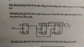
I have a sequential circuit (circuit in image below) and my objects is analyze this circuit. My result is counter circuit which count from 0 - 1 - 2 - 3 - 4 - 5 - 0... But when i tested in Proteus, it couted 0 - 3 - 2 - 5 - 4 - 1 - 0...

So, anyone can help me?

Thank a lots.
 

Attachments

dl324

Joined Mar 30, 2015
16,942
Welcome to AAC!

Could you translate the problem text to English?

For either count sequence, you'll get the same results for Z. Are you supposed to determine the count sequence or Z?
 

Thread Starter

simpsons310

Joined Jun 3, 2017
6
Welcome to AAC!

Could you translate the problem text to English?

For either count sequence, you'll get the same results for Z. Are you supposed to determine the count sequence or Z?
Sure. Text: " Analyze sequential circuit below and describe the function? Supose the first state is 000"

Z always is 0. I only need the count sequence.

sorry for late reply.
 

WBahn

Joined Mar 31, 2012
30,072
Which flip flop is your lsb and which is your msb?

The sequence 0 - 3 requires two bits to change. But if you are starting out with all 0's then on the first falling clock edge your leftmost counter goes HI which means that the next counter gets a rising clock edge. Thus only one bit can change. But if your simulation is using rising-edge sensitive flip flops, then both of the first two counters will change state. So I suspect that your simulation is using positive-edge triggered JK flip flops.
 

Thread Starter

simpsons310

Joined Jun 3, 2017
6
Which flip flop is your lsb and which is your msb?

The sequence 0 - 3 requires two bits to change. But if you are starting out with all 0's then on the first falling clock edge your leftmost counter goes HI which means that the next counter gets a rising clock edge. Thus only one bit can change. But if your simulation is using rising-edge sensitive flip flops, then both of the first two counters will change state. So I suspect that your simulation is using positive-edge triggered JK flip flops.
I just have sovled my problem. Thank you very much. :D
 

Thread Starter

simpsons310

Joined Jun 3, 2017
6
So what was your problem? The polarity of the clock inputs, or something else?
Yeah, when I used positive-edge triggered JK flip flops, the result is 0 - 3 - 2 - 5 - 4 - 1. And when I used negative-edge triggerd JK flip flops, the result is 0 - 1 - 2 - 3 - 4 - 5.
 

WBahn

Joined Mar 31, 2012
30,072
Thanks.

Did you notice the steps I used to deduce this? They are more helpful than the solution to the problem. I asked what was possible with the circuit as shown and was it in any way consistent with the behavior seen. As shown, the first time any change occurs the only FF that can change state is just the first one since the others see a rising clock edge. Thus, if you are seeing more than one change initially, the others must be sensitive to a rising clock edge.
 

Thread Starter

simpsons310

Joined Jun 3, 2017
6
Thanks.

Did you notice the steps I used to deduce this? They are more helpful than the solution to the problem. I asked what was possible with the circuit as shown and was it in any way consistent with the behavior seen. As shown, the first time any change occurs the only FF that can change state is just the first one since the others see a rising clock edge. Thus, if you are seeing more than one change initially, the others must be sensitive to a rising clock edge.
Sure, I understood. But i didn't know how to describe it in English. I had to have my friend translate it but everyone was busy. Thus, I replied what I could think that time. LOL
 
Top