Analysing DAC actual performance

Thread Starter

Jack Tranckle

Joined Jan 20, 2016
73
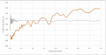
A rounded value is sent to the DAC via a microcontroller and represents frequency. I have measured each step of the MCP4921 DAC output, and compared it to the ideal rounded integer to see how much error is present. The value sent out is from an exponential calculation so the amount of descrete steps grows exponentially between each DAC data point. I understand that the DNL error has bigger effect when there are less discrete steps ,therefore there should be less error at higher frequencies. but looking at the graph, the actual values seems to be growing at higher DAC points, not tending towards the ideal voltage. what could be causing this? orange is the actual measurements, grey is the rounded value (ideal)
 

Attachments

Last edited:

Thread Starter

Jack Tranckle

Joined Jan 20, 2016
73
the measurement is taken with a picoscope and a multimeter. Both giving the same values. There is no DNL error on this graph, just the ideal rounded integers and then the actual output (orange). I just wanted to analyse the effects of the DAC errors. was surprised to find them increasing so linearly
 

Thread Starter

Jack Tranckle

Joined Jan 20, 2016
73
The exact frequency of a musical note is calculated within an arduino, and then rounded and sent to an external DAC. 10 bit DAC, so frequencies of up to 1024 can be achieved, where 1024 will output 5v (DACs max out) The voltage output of the DAC is used to drive a ramp oscillator. The ramp is reset precisely via the microcontroller, so any rounding error from the DAC does not effect the frequency, but instead will effect the amplitude of the ramp (as the DAC voltage determines the ramps rate of charge). The graph is showing the amplitude. The grey line is the calculated frequency inside the arduino, which is has been rounded to its nearest integer so that it can be sent to the DAC.

27.5 = 30
1012.89 = 1013

it does not consider any errors at all, just an ideal DAC. The orange line is the actual values that I measured using a multi meter at each note. Therefore comparing the two graphs, I should be able to analyse the DACs actual characteristics. As mentioned, I am expecting errors such as DNL but I am just slightly confused as to why the amplitude seems to be continuously rising. Would maybe the INL or another parameter of the DAC explain this ?

one more note, the relationship between each value sent to the DAC is exponential, therefore low values are very close together. and larger values are far apart. Im not sure if this could be a cause
 

MrChips

Joined Oct 2, 2009
30,712
The first common cause of noise on DAC output that increases with DAC amplitude is poor power supply decoupling.
Make sure that Vcc and GND are properly filtered with decoupling capacitors placed in parallel across the Vcc and GND pins at the DAC IC.
You can try a single 1μF or 10μF electrolytic capacitor.
 

OBW0549

Joined Mar 2, 2015
3,566
The first common cause of noise on DAC output that increases with DAC amplitude is poor power supply decoupling. Make sure that Vcc and GND are properly filtered with decoupling capacitors placed in parallel across the Vcc and GND pins at the DAC IC. You can try a single 1μF or 10μF electrolytic capacitor.
A noisy/unstable/improperly decoupled reference voltage for the Vref pin (pin 6 on the MCP4921) will do the same thing. Using a quality voltage reference is important for getting good DAC performance, especially at 12 bits and up.
 
Top