Facebook
 Google
 GitHub
 Linkedin
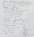
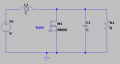
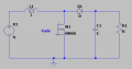
I have started analyzing the below circuit, i think it is boost circuit, i have not looked up the solution, the moment i check the solution i feel i have understood but reality is different

As soon as i saw the circuit first question comes to my mind is when we say load is it only resistor or it can be any combination?
As a first step i am assuming it is resistor alone.
1. I assume we give a fixed voltage let us say some 12V and i am switching the MOSFET at every 20Khz
Step1: when MOSFET is OFF the starting condition. The circuit changes to

The current in the inductor cannot change immediately it starts from 0, the voltage drops completely across the inductor V.
The voltage across capacitor cannot change immediately it starts from 0.
Both the current and the voltage will raise exponentially. The final current is I = V/R;
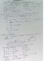
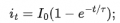
The current through inductor is

PWM is 20Khz with duty cycle of 50% (assumption) 25uS, the current would have attained some value of I1.
The capacitor would have charged during this time

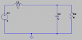
Step2: The MOSFET is ON condition the circuit becomes

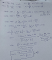
The capacitor discharges through R using below equation where V1 is the capacitor voltage at 25uS.

The load circuit now got isolated from voltage source and inductor, the inductor current will increase since there is no load, but what happens to the increased current, i am not sure. Please guide me so that i can put some values and see actually how the circuit increases the voltage from 12V to 24V.
As soon as i saw the circuit first question comes to my mind is when we say load is it only resistor or it can be any combination?
As a first step i am assuming it is resistor alone.
1. I assume we give a fixed voltage let us say some 12V and i am switching the MOSFET at every 20Khz
Step1: when MOSFET is OFF the starting condition. The circuit changes to
The current in the inductor cannot change immediately it starts from 0, the voltage drops completely across the inductor V.
The voltage across capacitor cannot change immediately it starts from 0.
Both the current and the voltage will raise exponentially. The final current is I = V/R;
The current through inductor is
PWM is 20Khz with duty cycle of 50% (assumption) 25uS, the current would have attained some value of I1.
The capacitor would have charged during this time
Step2: The MOSFET is ON condition the circuit becomes
The capacitor discharges through R using below equation where V1 is the capacitor voltage at 25uS.
The load circuit now got isolated from voltage source and inductor, the inductor current will increase since there is no load, but what happens to the increased current, i am not sure. Please guide me so that i can put some values and see actually how the circuit increases the voltage from 12V to 24V.
Attachments
-
 5.7 KB Views: 0
 -
 6.2 KB Views: 0
 -
 2.7 KB Views: 0
 -
 2.5 KB Views: 0