Analog To Digital Signal Converter

Status
Not open for further replies.

Thread Starter

820L

Joined May 14, 2025
30
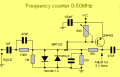
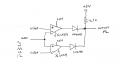
I need a circuit that will convert an analog signal of up to 12 volts to a square wave of 0 to 5 volts. I tried to
simulate the circuit with LTSpice using different values for HiRef and LoRef but it failed. I attached the circuit
schematic. I hope someone can help me with this.

thanks
 

Attachments

Papabravo

Joined Feb 24, 2006
22,072
Since the outputs of an LM339 are open collector, the diodes are unnecessary. They are backwards in your diagram and will never result in a low output.
 

Ian0

Joined Aug 7, 2020
13,118
An LM339 can only sink current. No current flows OUT of the output. Therefore no current can flow through your diodes.
Try turning them round.
I don't understand your description of what you want your circuit to do, but it looks like a window comparator to me.
 

Thread Starter

820L

Joined May 14, 2025
30
An LM339 can only sink current. No current flows OUT of the output. Therefore no current can flow through your diodes.
Try turning them round.
I don't understand your description of what you want your circuit to do, but it looks like a window comparator to me.
Hi

I want to be able to feed an analog signal in and get a square wave out. Yes, a window comparator is what
I was thinking.
 

LowQCab

Joined Nov 6, 2012
5,101
Depending on exactly what You are trying to accomplish,
a 7555 Chip may be the simplest solution.
It Flips and Flops at 1/3 and 2/3 of the Supply-Voltage, maybe that'll work for You.
.
.
.
 

crutschow

Joined Mar 14, 2008
38,423
Thanks. I will look into that!
Below is the LTspice sim of a circuit using the 555 as suggested by LQC:
The output goes high when the TRIG input drops below 1/3Vcc (1.67V) and goes low when the THRS input goes above 2/3Vcc (3.33V)

1747263857265.png
 
Last edited:

BobTPH

Joined Jun 5, 2013
11,489
You say the signal is “up to 12V.” What should your circuit do when it is 1V? What if it goes negative? What waveform(s) might it be?

What is the frequency and duty cycle of the square square wave output

Is this for an actual project, a homework assignment, or just for learning?

In any case, a better specification of the input and output is needed.
 

Thread Starter

820L

Joined May 14, 2025
30
I appreciate all of the responses. After giving this more thought, I have come up with what I believe to
be a set of specs for the circuit based upon your responses.

1) Attenuate the input voltage if it is above 5 volts.
2) Amplify the input voltage if it is below 3.3 volts.
3) Accept any type of waveform, ac or dc, from 1 Hz to 60MHz.
4) Protect the circuit from negative voltages and voltages say above 15 volts.
5) Provide a 5 volt square wave output with the same frequency and phase as the input.
6) Low noise output suitable for digital circuit interface.

Probably a pretty tall order.
 

MisterBill2

Joined Jan 23, 2018
27,366
I did have second thoughts that possibly the TS was wanting a voltage to frequency converter. But now it seems more like an input circuit for a frequency counter. That would be a good place to look for a sample circuit . My HP counter works with about 100mV to several volts.
 

Thread Starter

820L

Joined May 14, 2025
30
I did have second thoughts that possibly the TS was wanting a voltage to frequency converter. But now it seems more like an input circuit for a frequency counter. That would be a good place to look for a sample circuit . My HP counter works with about 100mV to several volts.
Would this circuit work? Not sure what voltage should be used for VCC?
 

Attachments

Status
Not open for further replies.
Top