Analog To Digital Signal Converter ..#2

nsaspook

Joined Aug 27, 2009
16,370
Why can you not input the sinewave into the digital input?
Does the input know the difference between a sinewave and a square wave?
(I am trying to understand why you think that you cannot do this, just for my clarification.)

What is the difference between a digital signal and an analog signal?
A digital signal is analog.
Not exactly the same because of what's important here, time.

A digital signal is analog but it's a very fast analog signal at the edges.

A fast, clean square wave from a well designed sine converter has a much faster slew rate (rise time slew rate of the digital signal) during flips vs the slew rate of the sinusoidal at the zero-crossing. This can reduce jitter (with even small amounts of noise) when using precision frequency sources up to x10 with fast, 5ns or less chips. Much faster slew rate, much less time for some random signal to affect the digital changes during flips.
 
Last edited:

nsaspook

Joined Aug 27, 2009
16,370
Last edited:

Thread Starter

Peppino59

Joined May 15, 2025
9
Why can you not input the sinewave into the digital input?
Does the input know the difference between a sinewave and a square wave?
(I am trying to understand why you think that you cannot do this, just for my clarification.)

What is the difference between a digital signal and an analog signal?
A digital signal is analog.
The counter that I have to use in the STM32 only wants TTL square wave, the counter does not accept 10Mhz sinusoidal, I am building a GPSDO 10Mhz PLL
 

MrChips

Joined Oct 2, 2009
34,956
The counter that I have to use in the STM32 only wants TTL square wave, the counter does not accept 10Mhz sinusoidal, I am building a GPSDO 10Mhz PLL
That still does not answer the question.
What is the difference between an analog signal and a digital signal?
A digital signal is still analog.

How do you know that the STM32 does not accept 10 MHz sinusoidal?
Have you tested it?
What does the 10 MHz signal look like on an oscilloscope with the input channel set to DC?
 

Thread Starter

Peppino59

Joined May 15, 2025
9
That still does not answer the question.
What is the difference between an analog signal and a digital signal?
A digital signal is still analog.

How do you know that the STM32 does not accept 10 MHz sinusoidal?
Have you tested it?
What does the 10 MHz signal look like on an oscilloscope with the input channel set to DC?
The 10Mhz of the Trimble 72345 OCXO has a perfect sine wave of 2Vpp has no DC output and 50 hom
 

MrChips

Joined Oct 2, 2009
34,956
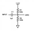
Try this circuit.

GPIO AC input.jpg

For 10 MHz, you can make C1 as small as you wish, even as low as 10 pF.
The reactance of 1 nF at 10 MHz is 16 Ω.

If you want to present a 50 Ω load, change R1 and R2 to 100 Ω each.
 

Thread Starter

Peppino59

Joined May 15, 2025
9
Try this circuit.

View attachment 349811

For 10 MHz, you can make C1 as small as you wish, even as low as 10 pF.
The reactance of 1 nF at 10 MHz is 16 Ω.

If you want to present a 50 Ω load, change R1 and R2 to 100 Ω each.
I'm using a STM32F411CEU6 black Pill, I've already tried it doesn't work, I tried on PA15, PA5, PA0, PB9, I've tried them all it doesn't work, I don't have to use a Timer I have to use a counter so that system doesn't work, I'll do it this way:
OCXO (10 MHz sinusoid)

LT1719 comparator

SN74LVC1G17 buffer (level 3.3 V)

PA15 (TIM2_CH1)
 

nsaspook

Joined Aug 27, 2009
16,370
If you are measuring time, period, frequency on an electronic instrument, which GPS 10MHz signal is better as the standard to measure other signals for a digital signal measuring/control device.? Better is defined a more stable as a reference that should be 10X better than what's being controlled or measured.
1748048780699.png

Square wave or Sine wave?
1748048835657.png
Output.
1748048857666.png
Input.
 
Top