Analog Sound Mixer Power Supply NOISE problem

Pyrex

Joined Feb 16, 2022
526
Dear Pyrex,
Nice tip. No oscilloscope here....i'll buy one someday. Had a tube one that broke......I tested Power supply on it's OWN, with some loads attached, except for the -15V. I cannot say what ripple I have without an oscilo, I know, but I tested with multimeter and it's dead stuck right to the third decimal all the time. On the input there are 3x4700uF that's more than 14000uF, should be no ripple on the input, so I expect none on the output.
-------------------
When I initially tested the MIXER with my PSU, something very interesting happend though.
Please bare with me a minute :)
So I had my PSU board on my working table, with the toroidal transformer next to it, center tap connected to ground PSU, as in the schematic. The mixer was sitting on another small table, I hooked it's power inputs to my psu via some long wires, just for testing. Everything worked GREAT. NO hum no buzz, no hiss, no nothing, all voltages measured were JUST PERFECT. I was so happy. :)
Ok.
If you have no oscilloscope, you can check ripple with an ordinary DMM in ACV mode. Important: add a capacitor in series with the probe. 0.1uF 100V is ok for the check .

" Everything worked GREAT"
Can you unscrew this special transformer and change it's position in the case for the test? It seems to me, the leaked magnetic field make the hum and buzz.
If this is not possible, can you found an another transformer for the test , a cheap one and with no internal screens, with primary 230V and centertapped 15V-0-15V or 20V-0-20V Or a transformer with two secondaries 15-20V each, power rating about 50VA. Disconnect all three wires ( 15VAC-O-15VAC) from your special transformer and reconnect them to this test transformer. Your mixer should work, probably, a very weak buzzing will be heard, this is normal.
We will determine, do the special transformer create the problem
 

Thread Starter

GeekTm88

Joined Sep 8, 2023
21
OK GUYS, I HAVE SOME PROGRESS :)I was looking at Behringers original SMPS schematic, I foud a schematic for an identical ONE, but my does not need the 5V rail . So ignore that 5V Rail.
To put it simple....I need +15 -15V to drive the OPAMPS, basically make the mixer work soundwise, 12 V for the inbuilt digital effects unit, and 48V phantom power.
Looking at that schematic I see that some grounds are ANALOG grounds (OP AMPS and Phantom ), some are DIGITAL (for the effect unit).
My PSU board, has three TOTALLY Independendent power circuits: 12V + -, +15 CENTERTAP -15, 48V + -
Each of those three PSU come from their own secondary windings, own rectifier bridge, own filtering, own stabiliser - SO THEY ARE GALVANIC ISOLATED, NOTHING IN COMMON.
I did a test today.
Hooked back the center tap wire, and only sent power to the +15, -15, ANAOG GROUND mixer power inputs.
AND TO MY SURPRISE, IT WORKED LIKE A CHARM, NO NOISE AT ALL. That's why with open box when I tested initially I had no buzz, because I remembered I anly connected this analog audio part.
So today I moved on....I connected +12 to the 12V input and GND from my 12 Supply to DIGITAL GROUND pin, and all hell returned....noise was going crazy. Disconnect the 12 V part, noise on the analog part stops.

The Mixers power input pins are:
1 +15V Analog
2 -15V Analog
3 Analog Ground
4 +48V Analog
5 NOT USED IN MY MIXER (for others it's 5V)
6 GROUND?? (I DO NOT KNOW IF ANALOG OR DIGITAL)
7 +12V Digital
8 Digital Ground

Through the mixers own wireing in the internal PCB's I've tested that 3 and 8 have contact. 6 does not have contact with neither 3, nor 8.

I also put a 100nF cap paralel to 10Ohm between analog and digital ground pins - noise went down a very very tiny bit, but still unusable mixer.
I put then only the 100nF cap betheen AN_GND and DIG_GND the high frequencies of the noise were gone, now only a loud hum remains - still mixer is unusable.

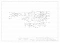
I am posting a pic of Berry's original PSU (ignore the 5V part), and the schematics of the mixer here ignore the effects unit, everything else is the same.
SMPS.jpg
 

Attachments

BobTPH

Joined Jun 5, 2013
11,609
With no power supply connected measure the resistance between AGND and DGND.

If there is no connection, they must be using opto isolators or something else to get signals back and forth.
 

Thread Starter

GeekTm88

Joined Sep 8, 2023
21
PROBLEM SOLVED!!!
I just added a 100nF cap on the analog GND connection and ,,,,yup.....al problems gone, just like magic.
All that trouble for nothing.
I am thinking now to modify the PSU to make the regulation in switched mode, for less thermal power loss.
You now any good ready made DC-DC step-down module PCB's that can handle the 23V input, output 15V? Current....min 3-5A for longevity. And also negative variant? (for the -15 line)?
LOTS OF THANKS GUYS!
 

crutschow

Joined Mar 14, 2008
38,670
I just added a 100nF cap on the analog GND connection and ,,,,yup.....al problems gone, just like magic.
So between what two points did you connect this capacitor?
I am thinking now to modify the PSU to make the regulation in switched mode, for less thermal power loss.
I would not do that, unless you really need to, as switched-mode supplies are inherently more noisy.
 

Thread Starter

GeekTm88

Joined Sep 8, 2023
21
So between what two points did you connect this capacitor?
I would not do that, unless you really need to, as switched-mode supplies are inherently more noisy.
Hi there,
I added it between PSU gnd which is also connected to the center tap of transformer and the Analog GND input pin of the mixer. I've also increased the value now, maybe there is a little bit of difference, or maybe it's just me....now it has 3x 100n/250V in paralel, so yeah it's 300nF now. I looked for 220 or 470 but I miss them now in my stock.
 

MisterBill2

Joined Jan 23, 2018
27,977
I suggest adding a bit of resistor between the first capacitor and the second capacitor on both positive and negative sides, That will add a bit of filtering and reduce the heat load of the regulators. AND add the 0.1 mfd cap as the application notes always caution.
But now it seems that the noise is from the 1 volt digital section.
AND 100nf from where to where?? I did not get where it was across.
 
Top