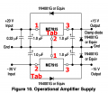
1. I can recommend you to disconnect all the three wires - +15,-15,GND from the mixer. Put a load to both regulators- two resistors , say 20 Ohm 15W . Reconnect the broken GND wire and power on the circuit. Now you can test the circuit with an oscilloscope. What ripple is on the 7815' ( 7915") input. What ripple is on the both outputs.
2. Can you make a simple sketch, how the GND wiring is performed? I'm afraid, there's an undesired loop or an undesired connection to the metal casing
Maybe the drawing is.... yeah, a bit unclear for you, I did it in a hurry, sorry guys...... but to me it's clear, and it's 100% connected correctly.
7815 Positive regulator - Pin 1 INPUT (i wrote I on schematic), Pin 2 and HS are GROUND, 3 OUTPUT (I wrote OUT on schematic)
7915 Negative regulator - Pin 1 GROUND, Pin 2 & HS are INPUT (i wrote I on schematic), Pin 3 OUTPUT (I wrote OUT on schematic)
HS=heatsink
THE PROBLEM IS NOT IC CONNECTIONS NOR HEATSINK CONNECTIONS/SHORTS PROBLEMS - 100% SURE. I'm not a newb ))))
Dear Pyrex,
Nice tip. No oscilloscope here....i'll buy one someday. Had a tube one that broke......I tested Power supply on it's OWN, with some loads attached, except for the -15V. I cannot say what ripple I have without an oscilo, I know, but I tested with multimeter and it's dead stuck right to the third decimal all the time. On the input there are 3x4700uF that's more than 14000uF, should be no ripple on the input, so I expect none on the output.
The only connections to the mixer are through it's original PSU connector, one pin there is GND, and my PSU GND is connected only to that, nothing else. I made no other ground stars or whatsoever GND CHASSIS connections, just not to risk creating ground loops. the only connections to the chassis, are from the mixers pcb via the metal screws (the factory connections).
When I initially tested the MIXER with my PSU, something very interesting happend though.
Please bare with me a minute
So I had my PSU board on my working table, with the toroidal transformer next to it, center tap connected to ground PSU, as in the schematic. The mixer was sitting on another small table, I hooked it's power inputs to my psu via some long wires, just for testing. Everything worked GREAT. NO hum no buzz, no hiss, no nothing, all voltages measured were JUST PERFECT. I was so happy. So without any other thoughts, I assembled it all up, put the toroidal transformer in the mixer case, I told you, I custom ordered it, with perfect dimensions, clearances - everything, also put my PSU PCB inside the mixer chassis, I made the proper wire connections to the power inputs, and put all screws. I powered it all up, without any second thoughts, and it powered up BUT THE NOISE MADE IN UNUSABLE. I've said to myself, well it worked perfect with PSU and transformer outside the box, what the hell??? Although I've paid extra to the transformer company to make it very low magnetic field and all the bells and whistles, I belived that electromagnetic interference was the suspect. SO, I bought a plastic box for the transformer, to get it out of the mixer case. I now have the AC voltages coming into the mixer through a high quality German made 7 copper wire cable, each wire 1mm copper section. Hoping for the best, I powered it up again, and the noise was still there. I was really mad now, I could not understand why, I was sure it was EMI to blame.
Then I started fiddling, until I discovered that cutting the center tap connection from the mixer input GND pin, solved the noise (the red X on my schematic), but it f***ed up the voltages. You can only imagine how sad I am now with this project. I don't now what to do.....but maybe the answer to the problem is somewhere hidden in my little story I've just told you.
I forgot to mention that my PSU board (still inside the mixewr case), is mounted on a wood plate, and is not thouching the metal chassis at any point.
I've read on the internet, I've done extensive reasearch on this noise problem, that some analog engineer "gurus", recommend using a thermistor or a bridge rectifier to connect center tap to chassis. What's this all about? you guys have any experirnces with such practices? I've never seen them...
So I had my PSU board on my working table, with the toroidal transformer next to it, center tap connected to ground PSU, as in the schematic. The mixer was sitting on another small table, I hooked it's power inputs to my psu via some long wires, just for testing. Everything worked GREAT. NO hum no buzz,
Is it possible for you to replicate that configuration?
Certainly there was some type of significant change from there to putting in the mixer box.
The task is to determine what that was.
I am thinking now maybe a bad transformer, or a bad rectifier bridge, I've noticed it's a little warmer this + - 15V one, I.m drawing 1.6 Amps combined from it (max 800 mA positive and max 800mA negative), and it's a brand one, DIOTEC, rated at 8A, more than 4 times than what is consumed. It puzzled me why I feel it warmer, the other rectifiers for the other voltages, are the same type, and are stone cold, with simmilar current demands from the other circuits.
HOW DO I test the transformer for shorts / faults ?
Please help me, so I am sure I am not omitting something, I am very tired now, but if it is at fault, being under warranty, the manufacturer has to make me a new one.
Please help me with how to make a COMPLETE fault check with multimeter on the transformer.
Thnx guys.
Check the resistance between the input and output windings, and the input and output windings to the transformer case.
All should read above full scale on the multimeters highest resistance range.
That will likely dissipate about 2W in the bridge so that warmth would be expected.
Check the resistance between the input and output windings, and the input and output windings to the transformer case.
All should read above full scale on the multimeters highest resistance range.
Dear Sir,
I'll check the resistance of the windings tomorrow.
I believe all should be in the ohms range. To case, yes + infinite we should have, but here I have no case, it's a round toroidal transformer not a classic one. InBetween the secondary windings, if any "leak", how to check?
My secondary looks like this in section:
Output 1 = 12 V (winding no 1)
Wire red
Wire red
Output 2 = 15 V (winding no 2) with center tap
Wire - blue
Wire - orange
Wire - blue
Wire for screen - green and yellow
(I guess they made just a wire wrap winding)
Output 3 - 48 V (winding no 3)
Wire - black
Wire - black
1. There is no standard for pin locations and function assignments for this type of component.
2. Because there are no pin numbers on the component decal, whether or not it is connected correctly cannot be determined. As far as sit goes, the schematic is correct.
However, if you examine the device pinout on the datasheet, you will see that he has the connections correct for the physical locations of the pins. His decal matches the physical arrangement of the component, and the net names and connections are correct for the circuit.
Having a schematic mimic the physical layout of a circuit assembly is something I often argue against. I think it is a bad habit to form, because a schematic's primary job is to convey the intent of the designer; it is *not* an assembly drawing or a wiring diagram. For example, I have 9 different decals in my design library for the 555. Some have different pin spacings because the components nearby on the schematic would have forced a bunch of distracting and confusing zig-zagged nets. Many have the pins in various locations around the decal to make the signal flows in and out easier to grasp. Example: many circuits have pins 2 and 6 connected together. Putting them on opposite sides of a schematic decal and running a net all the way around the part, crossing over multiple other nets, is worse than dumb. It is creating the possibility of an error where there is no cause for one.
1. There is no standard for pin locations and function assignments for this type of component.
2. Because there are no pin numbers on the component decal, whether or not it is connected correctly cannot be determined. As far as sit goes, the schematic is correct.
However, if you examine the device pinout on the datasheet, you will see that he has the connections correct for the physical locations of the pins. His decal matches the physical arrangement of the component, and the net names and connections are correct for the circuit.
Having a schematic mimic the physical layout of a circuit assembly is something I often argue against. I think it is a bad habit to form, because a schematic's primary job is to convey the intent of the designer; it is *not* an assembly drawing or a wiring diagram. For example, I have 9 different decals in my design library for the 555. Some have different pin spacings because the components nearby on the schematic would have forced a bunch of distracting and confusing zig-zagged nets. Many have the pins in various locations around the decal to make the signal flows in and out easier to grasp. Example: many circuits have pins 2 and 6 connected together. Putting them on opposite sides of a schematic decal and running a net all the way around the part, crossing over multiple other nets, is worse than dumb. It is creating the possibility of an error where there is no cause for one.
Dear AnalogKid,
You are absolutely right. 100% percent. Schematics should be made in the most optimum way, they need to reflect the design - not the wire diag. / pin-out. That's what I was taught in school too. I got creative with the negative regulator decal, just because I was in a hurry and had the real component pins in mind - but still - there is no standard for those regulators - designer discretion applies, you are right.
Very good remarks. I like the fact that you stick strictly to the designing rules. I could have done the schematic in Pads, Orcad or EasyEda but I prefer good ol' paper for simple circuits. After all, we usually hand-write/draw quite rarely nowadays, everything is digital, so yeah...a little hand movement is good for our minds I guess.
This simple simple and again simple circuit , gives me headaches now.
I really appreciate that all of you are so willing to help. Nice community here
As I previously stated.
Measured resistance between any isolated windings should give an overrange reading on the highest resistance setting for the multimeter.
I got the protection diodes installed too on the ICs, and Stotkeys on the outputs for their lower voltage drops. Look, I meant no offence with my schematic, I drew there just the "main and important" stuff, so you all could get a rough idea.
Please, let's just not forget the main reason of the problem....the noise . I'm sure that it's not coming from my quickly hand-drawn schematic.
These standard jelly-bean Regulators have been laid-out in this exact manner for at least ~60 years,
and there is no simpler way to lay them out.
If anything is an accepted standard, then this is it.
Since the presented Schematic deviates from this ancient standard,
it raises questions about whether or not there may be some confusion
regarding how they should be connected.
It's a very legitimate point,
especially with such a basic Circuit, that's difficult to get wrong.
Dear Crutschow,
Sure, I'll re-check (for the 20th time...) tomorrow... it's 2AM in my timezone now. I'll let you know. You are very kind and on spot with your advices - many thanks. Also, will check your idea with the 10 Ohm resistance and 2 diodes + capacitor. Thanks for that article.
Again, I cannot overstate how glad I am to see such a good and helpful community here.
I thank you ALL.

 Facebook
 Google
 GitHub
 Linkedin



 ))))
))))