Facebook
 Google
 GitHub
 Linkedin
For a DIY project related to capacitive level sensing in drinking water I need some information regarding a suitable insulated conductor that can be used.
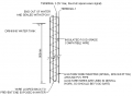
I am planning to use the insulated conductor as one of the terminals for the capacitive sensor probe.
I believe that normal insulated wires (flexible wires generally used in household wiring) are not properly waterproof (am I wrong?). Even if they do, I doubt whether the insulated material can be immersed in drinking water ("food safe")
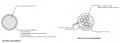
So as an alternative method, I have tried with a bare conductor wire through a flexible pvc tube. But I am not satisfied with the arrangement.
Any advice on suitable material/ conductor for this project.
I am planning to use the insulated conductor as one of the terminals for the capacitive sensor probe.
I believe that normal insulated wires (flexible wires generally used in household wiring) are not properly waterproof (am I wrong?). Even if they do, I doubt whether the insulated material can be immersed in drinking water ("food safe")
So as an alternative method, I have tried with a bare conductor wire through a flexible pvc tube. But I am not satisfied with the arrangement.
Any advice on suitable material/ conductor for this project.
")