Amplifier design

Thread Starter

gato pro

Joined Sep 18, 2020
18
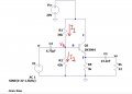
Hello, i need some help, i want to amplify –3dB a 1.5kHz signal with a maximum amplitude of 3V using the 2N3904 transistor.
I decided to use the common collector configuration, since I need a voltage gain of approximately 0.7 (-3dB = 20log | Av |).
For the design I chose ICQ = 3.25mA, VCEQ = 10V and Vcc = 20V to have a maximum symmetric excursion.

For analysis in dc, i take IC = IE and making RE = (Vcc-VCEQ) / ICQ calculate RE = 3k ohms.
From the data sheet, where are the graphs of the h parameters as a function of the current Ic, i take the value of hfe=140 (for ICQ = 3.25mA)
Then i calculate IB=IC/hfe= 23.21uA

VB= VBE + VRE = 0.7V + 10V = 10.7V

Assuming I2 = 10xIB --> I1 = 10xIB + IB = 11xIB, with this calculate the values of R1 and R2 as
R1=(Vcc-VB)/I1 = (Vcc-VB)/11xIB = (20V-10.7V)/(11x23.21uA) = 36k ohms.
R2= VB/I2 = VB/10xIB = 10.7V/10x23.21uA = 46k ohms.

Av = [ (RL || RE)(hfe + 1) ] / [ hie +(RL || RE)(hfe +1) ] --> RL = 22 ohms.

For the capacitors i calculate C1 = 1 / ( 2*pi*1.5kHz*RIN) where RIN = R1 || R2 || hie
for C2 = 1 / ( 2*pi*1.5kHz*Rout) where Rout = RE || RL

But when i plot Vi and Vo with ltspice, i dont get a correct wave form for Vo, because since the voltage gain is 0.7, and taking vi as 3V, making
Av = Vo / Vi, Vo should have an amplitude of 2.1V.

Someone would be so kind to tell me what I'm doing wrong please?
I have attached the ltspice files in case it works for you.
 

Attachments

Audioguru again

Joined Oct 21, 2019
6,673
It is obvious that the low current transistor cannot drive the 22 ohms load. Especially when the reactance of the 1.6nF output capacitor at 1.5kHz is 67k ohms then the 3V from the transistor is attenuated to only 0.00099V.
 

ronsimpson

Joined Oct 7, 2019
2,989
C2 = 1 / ( 2*pi*1.5kHz*Rout) where Rout = RE || RL
It is obvious that the low current transistor cannot drive the 22 ohms load. Especially when the reactance of the 1.6nF output capacitor at 1.5kHz is 67k ohms then the 3V from the transistor is attenuated to only 0.00099V.
I think you need to rethink the output capacitor. Cout and Rload and come up with a much bigger cap. (no Re) Not nf maybe uF. I did not do the math. It is just obvious. To quote the grate Guru.
 

Thread Starter

gato pro

Joined Sep 18, 2020
18
Thanks for answering, are there any design criteria for capacitors?
In some analyzes, more than anything for common emitter amplifiers, they usually choose that Xc1 <= Rin / 10, in this case i dont know if the design cosideratios that i take are correct, more than anything the consideration I make of I2 = 10 * IB
 

Audioguru again

Joined Oct 21, 2019
6,673
Thanks for answering, are there any design criteria for capacitors?
Of course the value of a coupling capacitor needs to be calculated for the lowest frequency used and for its reactance. Its reactance is like its resistance to the AC.
The formula for a capacitor value is 1 divided by (2 x pi x r x f). Where r is the reactance and f is the frequency.
But your simple circuit cannot drive a load as low as 22 ohms.
 

Audioguru again

Joined Oct 21, 2019
6,673
Your simulation shows that your peak (not RMS) input is 3V. Then the -3dB peak output is 2.121V. Then the peak current in the 22 ohms load resistor is 2.121V/22 ohms= 96.4mA. Since your RE pulls the output down and is 3k ohms then for it to produce -96.4mA then its power supply must be -291.4V, not the ground (0V) that you show.
 

Papabravo

Joined Feb 24, 2006
21,159
Yes, I have to obtain the values of the resistors and capacitors so that the circuit amplifies -3dB at a frequency of 1.5kHz and with an input signal of at most 3V amplitude
-3dB is not amplification it is attenuation. Unless you learned your mathematics in an alternate universe.
 

Thread Starter

gato pro

Joined Sep 18, 2020
18
Your simulation shows that your peak (not RMS) input is 3V. Then the -3dB peak output is 2.121V. Then the peak current in the 22 ohms load resistor is 2.121V/22 ohms= 96.4mA. Since your RE pulls the output down and is 3k ohms then for it to produce -96.4mA then its power supply must be -291.4V, not the ground (0V) that you show.
Would you help me get values to make it work please?
 

Thread Starter

gato pro

Joined Sep 18, 2020
18
Hello, thank you very much Audioguru again for the help, if it is not too much trouble I wanted to ask you how you did the analysis to reach the -3dB of attenuation at the output, that is, if you started from some assumption to obtain the values of the resistors and capacitors, seeing the dc equivalent circuit, i calculate IcQ, VceQ, Ib and with IcQ / Ib I got betha.
 

Audioguru again

Joined Oct 21, 2019
6,673
1) I decided to use a 9V battery.
2) I decided to have an emitter current of about 1.5mA.
3) I decided to bias the base of the transistor at about half the 9V supply.
The emitter DC voltage is 4.5V - 0.65V= 3.85V.
Then the total emitter resistors are 3.85V/1.5mA= 2.57k and 0.707 x 2.57k= 1817 so I used 1.8K and the other resistor value is 2.57k - 1.8k= 770 but a simulation showed that 720 is needed which is not available so I used 680 ohms.

With an emitter current of 3.85V/(1.8k + 680)= 1.55mA then the base current is about 1.55mA/200= 7.8uA (200 is the typical beta). Since the minimum beta is 100 then I decided the base voltage divider should have a current of 30 times the 7.8uA= 234uA. 4.5V/234uA= 19.2k so I used 20k resistors.

I decided to let the input capacitor value pass frequencies above half the 1.5kHz frequency so a cutoff frequency of 75Hz would be used then the input capacitor is 0.22uF.
 

Thread Starter

gato pro

Joined Sep 18, 2020
18
1) I decided to use a 9V battery.
2) I decided to have an emitter current of about 1.5mA.
3) I decided to bias the base of the transistor at about half the 9V supply.
The emitter DC voltage is 4.5V - 0.65V= 3.85V.
Then the total emitter resistors are 3.85V/1.5mA= 2.57k and 0.707 x 2.57k= 1817 so I used 1.8K and the other resistor value is 2.57k - 1.8k= 770 but a simulation showed that 720 is needed which is not available so I used 680 ohms.

With an emitter current of 3.85V/(1.8k + 680)= 1.55mA then the base current is about 1.55mA/200= 7.8uA (200 is the typical beta). Since the minimum beta is 100 then I decided the base voltage divider should have a current of 30 times the 7.8uA= 234uA. 4.5V/234uA= 19.2k so I used 20k resistors.

I decided to let the input capacitor value pass frequencies above half the 1.5kHz frequency so a cutoff frequency of 75Hz would be used then the input capacitor is 0.22uF.
Thank you very much, you helped me a lot!!!
 
Top