The theoretical maximum efficiency of a class B amplifier is 78.5%.
Using a full wave rectifier and capacitor filter, the DC output current is 0.62 times the secondary AC current and the DC output voltage is 1.41 times the secondary RMS AC voltage.
VAC = secondary RMS AC voltage
IAC = secondary RMS AC current
VDC = DC output voltage
IDC = DC output current
W = amplifier output power.
Taking the amplifier efficiency into account: IDC x VDC = W / 0.785
IAC = IDC / 0.62
VAC = VDC / 1.41
Transformer VA = IAC x VAC = IDC / 0.62 * VDC / 1.41 = (IDC x VDC) x 1.14
So Transformer VA = (W / 0.785) x 1.14 = 1.45 x W
So a bare minimum of 45% more than the amplifier output power.
Also, are the diodes i used in the rectifier enough? The 1N4003G have a reverse voltage of 200 V and Curent of 1 A? I think I need to change the diodes to what can support 3A? Am I correct?
i used the 1n5402G diodes with 200 V and 3 A. added the 10000uF capacitors. it has 51 V and -51V. Do I need to treat the amplifier as a load for the supply and get its equivalent impedance and use it as a load for the supply? its only powering it to half of what it should. sorry, i still cant figure it out.
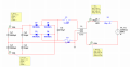
i used the 1n5402G diodes with 200 V and 3 A. added the 10000uF capacitors. it has 51 V and -51V. Do I need to treat the amplifier as a load for the supply and get its equivalent impedance and use it as a load for the supply? its only powering it to half of what it should. sorry, i still cant figure it out. View attachment 128245
You have a 100uF capacitor across the transformer secondary. That would have an impedance of 31Ω and so a current of 1.6A would flow through that capacitor - not good. For the simulation, remove that capacitor. In the real world you might connect a capacitor with a much lower value, perhaps 100nF, to reduce high frequency interference from the mains supply reaching the amplifier.
I was speaking for a practical situation.
If you choose your transformer depending on your sim you would be wrong.
You need plenty of extra power for the bass peaks.
Just connect amp to that PSU circuit and test your simulation. Why are you worried about "equivalent impedance" ?
And change those two 104uf to 100nf.
I see two possible problems with the amplifier.
The maximum output voltage swing from Q2 is limited by the voltage drop across the emitter resistors to about 75% of the supply voltage.
Also, the diodes on the bases of the output transistors can turn off those transistors but the only source of current to turn them on is the 20k resistors. Try reducing the resistors in that chain by a factor of ten - 2k and 50Ω.
Do not assume a 30W will deliver pure 30W when you start designing first.
Properly designed ones can deliver what it states and even that is under certain conditions.
 Facebook
 Google
 GitHub
 Linkedin