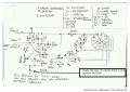
Alternator as adjustable output DC generator

debe

Joined Sep 21, 2010
1,419
If you need about 12-14v dc why disconect the built in regulator. All you needed was a small 12v lead acid battery conected, it will supply the necessary voltage & current automaticly no matter how many tools you hook up. To me you have over complicated the whole deal.
 

Thread Starter

papagayor

Joined Dec 20, 2025
18
If you need about 12-14v dc why disconect the built in regulator. All you needed was a small 12v lead acid battery conected, it will supply the necessary voltage & current automaticly no matter how many tools you hook up. To me you have over complicated the whole deal.
Dear Sir, the olive harvester tools that it was going to feed, have different working voltages also have different compatible feeding sources, some work with a 12V over 70Ah car battery, and some with generators with stabilizers. Plus this they have different voltage input from 12V (in true 13.5) to over 20V. So thought to cover every situation. But finally, and because cannot find a circuit or a module to do this job, I decided to use an electronic controlled voltage regulator connected on a small 12V-7Ah battery to feed rotor, a voltage meter to watch alternator output and probably high current (25-30A) boost controller for over 12V tools. I didn't know that it would be so difficult to find a module for this, also some regulators online posts in Greece (Yamastik, NOVA), said that they just can work by just connect them on an alternator, that's the other reasons that removed the internal regulator. But the posts have messed things up, as they work only with alternators having D+ output, not every car alternator. Also, they need the petrol engine that is rotating the alternator to work at almost full rpm's, I didn't want this, it's not good for engine. In every case my approach is to have the full control of construction, and to be able changing parameters depending on different conditions. I attach a circuit that someone posted in a forum showing a regulator supposed to work with my construction. Thank you for your time sir.
 

Attachments

Last edited:

MisterBill2

Joined Jan 23, 2018
27,552
That circuit in post #22 may be a brilliant bit of engineering but it is a challenge to follow.

How well do those different tools work when powered by just 13.5 volts??? It might work well to simply use the basic alternator output to power every one of them.

BUT you have another problem, which is that the tools made to use a rechargeable battery that is part of the tool package draw a lot of current, so you will need a heavy power cable.
 

Thread Starter

papagayor

Joined Dec 20, 2025
18
This circuit output voltage supposed to be controlled from the 12 positions switch by choosing the desired output every time, so for 12V tools have to choose probably position 7-8, and so on for over 12V up to 27V. I don't know how it works in true conditions, but made a test: I bought a regulator similar to this and connected it on my alternator, but the voltage did not changed by switch position, only by increasing rpm's, note that had no load on output of alternator and maybe it was a mistake, but anyway could not find some help for making it work, also as I said someone posted that the engine must run at almost full rpm and I don't like it. Trying to simulate the above circuit on easyeda but I have not the knowledge for this, so ....keep trying!!!
Attached some photos from the regulator that I bought to have a look.
 

Attachments

Last edited:

Thread Starter

papagayor

Joined Dec 20, 2025
18
This circuit output voltage supposed to be controlled from the 12 positions switch by choosing the desired output every time, so for 12V tools have to choose probably position 7-8, and so on for over 12V up to 27V. I don't know how it works in true conditions, but made a test: I bought a regulator similar to this and connected it on my alternator, but the voltage did not changed by switch position, only by increasing rpm's, note that had no load on output of alternator and maybe it was a mistake, but anyway could not find some help for making it work, also as I said someone posted that the engine must run at almost full rpm and I don't like it. Trying to simulate the above circuit on easyeda but I have not the knowledge for this, so ....keep trying!!!
Attached some photos from the regulator that I bought to have a look.
This link shows what type of alternators are compatible with this regulator: https://agro-net.gr/ανταλλακτικα-ελ...δυναμο-ελαιοραβδιστικων-12v-100a-με-βιδα.html
 

MisterBill2

Joined Jan 23, 2018
27,552
I suggested putting a changeable voltage divider to alter the feedback offset. THAT would have the original alternator doing the work. Does anyone else think that could work??
 

Thread Starter

papagayor

Joined Dec 20, 2025
18
I suggested putting a changeable voltage divider to alter the feedback offset. THAT would have the original alternator doing the work. Does anyone else think that could work??
Please sir, how could I do this procedure? Can it handle all 12-24V and 25-30A peak (normally 8-12A) that tools need? If you have a circuit please post it. Thank you again.
 
Last edited:

MisterBill2

Joined Jan 23, 2018
27,552
I gave a rather detailed explanation of the better scheme in post#19. WHAT IT DID WAS TRICK THE REGULATOR into increasing the output until it sees 12 volts on the regulator voltage sense input. That scheme probably would also work with the original regulator in the alternator, BECAUSE many of the internal alternators use an external sense input.
The method of tricking the regulator was to increase the voltage output required to satisfy the regulator. It should be possible to do that with just a series resistor.
BUT because I do not have a copy of the original regulator connections I am not able to provide any additional details. Do you still even have the original internal regulator??
 

MaxHeadRoom

Joined Jul 18, 2013
30,666
I have used the circuit from https://forum.allaboutcircuits.com/threads/6-volt-dynamo-regulator.209192/ for DC Magnet cranes of 240vdc/100amp down to 24v applications.
It is an old circuit I came up with a few decades ago, and could be brought up a little more modern, But they have been in operation for several years.
Modern auto regulators were required to use PWM due to the introduction of radio interference of the simple switching version originally used.
The one I wuoted is of the former style, but works OK where this is not an issue.
It would be very simple to make it adjustable over a range, if needed.
 

Thread Starter

papagayor

Joined Dec 20, 2025
18
I gave a rather detailed explanation of the better scheme in post#19. WHAT IT DID WAS TRICK THE REGULATOR into increasing the output until it sees 12 volts on the regulator voltage sense input. That scheme probably would also work with the original regulator in the alternator, BECAUSE many of the internal alternators use an external sense input.
The method of tricking the regulator was to increase the voltage output required to satisfy the regulator. It should be possible to do that with just a series resistor.
BUT because I do not have a copy of the original regulator connections I am not able to provide any additional details. Do you still even have the original internal regulator??
Thank you sir but I don't have the original regulator, maybe I can find a similar one and try to fit it on alternator to check if can work by this way about "tricking" it.
 

Thread Starter

papagayor

Joined Dec 20, 2025
18
I have used the circuit from https://forum.allaboutcircuits.com/threads/6-volt-dynamo-regulator.209192/ for DC Magnet cranes of 240vdc/100amp down to 24v applications.
It is an old circuit I came up with a few decades ago, and could be brought up a little more modern, But they have been in operation for several years.
Modern auto regulators were required to use PWM due to the introduction of radio interference of the simple switching version originally used.
The one I wuoted is of the former style, but works OK where this is not an issue.
It would be very simple to make it adjustable over a range, if needed.
I had a look on it but need some explanations: has a battery need to be connected on this circuit or it will be self-exited and feeded from alternator? suppose I can replace R1 with some resistors as a voltage divider fro controlling output current, also does this need a load to be on circuit to work or it produce the selected output voltage only by adjusting it with resistances? Thanks a lot
 

MaxHeadRoom

Joined Jul 18, 2013
30,666
I used a simple series resitor and zener depending on the voltage it was used on.
it is just a simple comparitor circuit.it does not require a load to work.
 

MisterBill2

Joined Jan 23, 2018
27,552
Do any others think that adding a zener diode voltage drop in the alternator regulator sense line is a reasonable scheme?? Or am I missing something. Since losing the sense line can result in a runaway output voltage, it seems reasonable to me. In an actual car alternator circuit the VR sense line is closer to the battery than the alternator output terminal.
 
Top