Facebook
 Google
 GitHub
 Linkedin
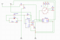
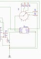
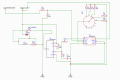
Hello, please I'm trying to make a circuit of this project: On a 6.5Hp petrol engine I fitted a car alternator with pulleys 2:1. Alternator is a BorgWarner 13.5V-130A, and I removed internal regulator so now have 2 free contacts for feeding rotor. The rotor resistance is 2.6Ω and by feeding it with 1.8V I had about 14V on output. I want to make this project for powering 1-3 olive harvester tools at different voltages and A but all the same (e.x. 12V-400W, 12V-800W, W is the peak), or 1 to 2 at about 12-21V and 800-1200W. The tools in normal working do not draw out more than 8-12A and only when they stack on tree they ask more, not over 25A. I'm going to feed rotor with a 12V-7Ah lead-acid battery with the attached circuit. My need is to control output at a stable voltage by a rotary switch and resistances, but when the connected tool or tools ask more current the circuit, to feed rotor with more current to balance the extra load. This approach is made because there are different olive harvesters, and I want to have complete control on construction's output, so that be able to feed every time each tool with the voltage and current that is needed. Please check the circuit and tell me if it's ok or need to make changes and where. It is based on 2 modules the XL as converter and LM as controller. Thank you