Alternating green and red LEDs discrete circuit

Tonyr1084

Joined Sep 24, 2015
9,744
We do. I asked if it was school work in post #2:


Then I gave him a circuit.
Yeah, that got by me too. I've been helping in the kitchen. Wife has been baking all day yesterday and today. Only able to poke in here for a few minutes at a time. Guess I lost track of some of the comments. My apologies.

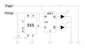
OK, here's my solution: Pin 3 is pulsing a square wave (clock) to the DDFF. IF the trigger (voltage) is high, Q follows D. /Q is opposite (complementary). Only one will be on at a time, depending on the trigger level at the time of the clock pulse. Therefore the clock pulse should probably happen at least 30 times a second (30Hz). No trigger, no voltage - no LED's lit. Voltage but no trigger, red LED (I see I forgot to identify which is which). Green is on bottom (the "Q" output) Red is on top (the /Q output). When trigger and voltage are present then the green LED will be lit. Resistance values are left unspecified because of the potential operating voltages. The TS will have to decide which values he wants where. Same for the cap.
1608581802317.png
 

dl324

Joined Mar 30, 2015
18,419
OK, here's my solution:
Well...

He wants to scale up the circuit I gave him to operate at 35V, maybe 45V. None of those IC's will work at that voltage.

He also wants to drive the LEDs at 20mA and a CD4013 won't do that.

Why use 4 or 5 transistors and a handful of resistors if you can use dozens of transistors in an IC that won't operate at the desired voltage?
 

Ian0

Joined Aug 7, 2020
13,165
After closer examination, with 5V power the red LED comes on. With "Trigger" (as someone called it), the green LED will come on too, but the red LED will remain lit. Unless they're powered from the same power source..
Just noticed I should have drawn 1N4148 at the top and the red LED underneath it, otherwise it isn't a common cathode LED, but it makes no difference to the operation.
IN not connected - red LED lights (goes without saying, really)
IN at 5V, cathode of the green LED is now at 2.8V (assuming 2.2V drop across a green LED). That means there must be 2.2V across the red LED and the 1N4148. 1N4148 drops 0.6V, leaving 1.6V across the red LED, which is not enough to light it.
To make really sure it works with lower than average voltage red LEDs and higher than average green ones, put another 1N4148 in series.
Easier at higher voltages, as you can use a zener and make really sure you have enough differential.
 

MisterBill2

Joined Jan 23, 2018
27,777
FIRST, the TS did not mention anything about flashing or blinking, only an input of 5 volts. There are lots of ICs that are not timers.
How about an op-amp powered by 5 volts with the LEDs in series across the 5, and resistors to set the current to 20mA for each one. and the opamp being set for a very high gain ( gets complicated.)

This is a 3 terminal device and so options are limited.If we assume that it is anodes (+) commoned then two comparators will do it, Each one doesa pull down lighting it's LED color depending on which comparator is active. The reference would be 5 volts, And the input voltage goes to the +input for the green led and the neg input for the red.
 

jpanhalt

Joined Jan 18, 2008
11,087
A discrete solution was requested. I suspect some sort of oscillator is needed. If one searches on "common cathode LED wig wag circuit," the TS should get lots of examples -- unless he is using Google and searched on some naughty things a little earlier.

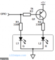
Here's a single transistor solution from that search:

1608584796820.png
Link: https://www.google.com/url?sa=i&url...ved=0CAIQjRxqFwoTCOjc1Z793-0CFQAAAAAdAAAAABAI
Of course, a 555 oscillator or any other can be substituted for the GPI0 input.

And here's a two transistor solution with no need for an oscillator:
1608584901979.png
Link: https://www.google.com/url?sa=i&url...ved=0CAIQjRxqFwoTCOjc1Z793-0CFQAAAAAdAAAAABAO

Of course, there are lots of other options. I have not tried any of them, as neither approach appeals to me.
 

jpanhalt

Joined Jan 18, 2008
11,087
Where did the idea of making them flash come from? Look at post #1, it is more like a voltage monitor.
Maybe here, post #1::
for example: initial state: external voltage 0V -> red led on, green led off
external voltage changes to +5V -> red led goes off, green led turns on
That describes a 0V to 5V square wave with some as yet undefined period or sequence. Either circuit I just posted is supposed to do that. Your problem?
 

Tonyr1084

Joined Sep 24, 2015
9,744
I'm reading a powered circuit that indicates whether there's a "Sense" or "Trigger" voltage present or not. If no Sense Voltage (SV) is present then the red LED should light. If SV is present then the red LED should go out and the green LED should light. Something we don't yet know for sure (unless I missed yet another factoid) is whether the sense is either held to ground when no voltage is present or not.

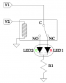
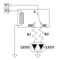
True, an op-amp could do the same thing, but the 555 IS an op-amp, basically. Little more than that, but nevertheless it is. Given the higher voltages that may be sensed, transistors (or maybe a MOSFET) may serve the bill. Possibly even a couple relays. I'll devote some grey matter to the "relays" part.
 

Tonyr1084

Joined Sep 24, 2015
9,744
Maybe here, post #1::


That describes a 0V to 5V square wave with some as yet undefined period or sequence. Either circuit I just posted is supposed to do that. Your problem?
Not necessarily. I think I read it to mean that if there's no Sense Voltage then the red LED should indicate the state of the sense line as being "Low". It would only change from red to green when a SV is present. A "Status" indicator.
 

Ian0

Joined Aug 7, 2020
13,165
Something we don't yet know for sure (unless I missed yet another factoid) is whether the sense is either held to ground when no voltage is present or not.
My circuit works (post #10) works in either case. It was used on a 96V supply, to indicate whether the output of an audio amplifier had exceeded a threshold (which was 90V)
 

Ian0

Joined Aug 7, 2020
13,165
Well, it certainly adds some hysteresis. Luckily the TS didn't mention anything about accuracy, frequency response or size constraints.
 

sghioto

Joined Dec 31, 2017
8,693
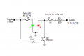
This is should meet the requirements of the TS with fewer components.
Con: does draw twice the current when the green LED is on.
EEE Alternate LEDs discrete.png
 
Last edited:

MisterBill2

Joined Jan 23, 2018
27,777
That's what makes it hard to answer a question intelligently when we don't have all the parameters.
I have made that point about getting adequate information perhaps a hundred times. No effect yet.
And since red and green LEDs have quite different forward voltage drops, of course they will need different resistors. And since they do not have a snap-action illumination threshold, external logic of some sort is required to make the switching work as desired.
 
Top