Facebook
 Google
 GitHub
 Linkedin
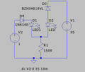
This will work from 15v to 35v but you'll have to change the current limiting resistors for the desired LED current.Would be possible to scale this to work with higher supply voltages, let's say between 15 and 35V?
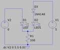
I tried to do it but Q3 in this circuit needs a 5V supply otherwise it doesn't turn off.