Facebook
 Google
 GitHub
 Linkedin
Yeah, that got by me too. I've been helping in the kitchen. Wife has been baking all day yesterday and today. Only able to poke in here for a few minutes at a time. Guess I lost track of some of the comments. My apologies.We do. I asked if it was school work in post #2:
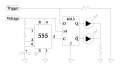
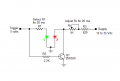
Then I gave him a circuit.
OK, here's my solution: Pin 3 is pulsing a square wave (clock) to the DDFF. IF the trigger (voltage) is high, Q follows D. /Q is opposite (complementary). Only one will be on at a time, depending on the trigger level at the time of the clock pulse. Therefore the clock pulse should probably happen at least 30 times a second (30Hz). No trigger, no voltage - no LED's lit. Voltage but no trigger, red LED (I see I forgot to identify which is which). Green is on bottom (the "Q" output) Red is on top (the /Q output). When trigger and voltage are present then the green LED will be lit. Resistance values are left unspecified because of the potential operating voltages. The TS will have to decide which values he wants where. Same for the cap.