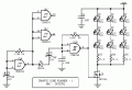
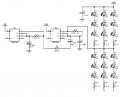
Here is a first pass at a fast/slow blink circuit.
R1-C1 sets the time for the fast and slow patterns.
R2-C2 sets the fast flash frequency.
C3 sets the slow flash frequency through D1.
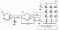
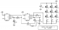
I don't think either of the last two circuits will work as there is no discharge path for the capacitor in series with the diode. When the diode cathode is pulled low there will be one slow charge cycle through the diode but thereafter the capacitor will remain charged and will no longer affect the timing of the second part of the circuit.
A diode to ground from the capacitor/diode junction (extra diode anode to ground) might fix this problem.
I see what you're saying. In the past a version of this circuit worked well for me, but there might have been other circuit interactions back then to prevent what you are describing. A diode across C2 certainly will aid in C3's operation.
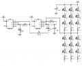
Post # 20, interesting. My take is there is a 5 Hz clock for 4017 & 5 sec. clock for select. When slow clock is low, A inputs are active, so LEDs 1-4 are on, & 5-8 are flashing at about 20 Hz. Slow clock high, B inputs active, 4017 active & LEDs light in sequence 0-7 for about 2.5 sec?
I see what you're saying. In the past a version of this circuit worked well for me, but there might have been other circuit interactions back then to prevent what you are describing. A diode across C2 certainly will aid in C3's operation.