 Facebook
 Google
 GitHub
 Linkedin
Hi, I am new to the forum and also electronics and cannot remember most of what I have learnt about electronics in high school.
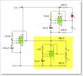
I want to build a warning beacon using LEDs. Attached is a diagram that I finally got working after a few hours.
The idea is to have a few (not sure how many) LEDs flashing in flip-flop fashion once every half second and then change to one flash every 1.5 seconds. BUT, I do not want two separate sets of LEDs like I have in my circuit, this is going to take up too much physical space. I want to use the same LEDs for bot the 555 timers.
Once this works I want to go one step further and change the timer in yellow section to drive a 4107 to have a chasing light for a few seconds followed by flashing lights and so on. But I am not there yet.
I hope my question is clear? I will really appreciate any advice.
Attachments
-
 64.2 KB Views: 45


