Completed Project Advice on connecting heater directly to SP2 relay of PID controller?

Thread Starter

Rahulk70

Joined Dec 16, 2016
536
Hello folks,

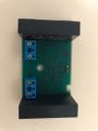
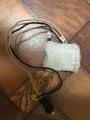
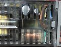
I have an old Omega CN-9121 PID Controller and a 105Watts 115V Fibre heater mantle with an inbuilt K-type CHromel-Alumel temperature thermocouple also attached into it. I plan to use the PID controller to control the temperature of the heater. Looking at the manual below:
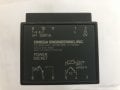
Manual for PID
I decided that I wanted to use the inbuilt SP2 relay in the PID controller. From the wattage of the heater, I know it would draw a maximum of only 1A and is going to be below that. The SP2 output from the PID has a small 5V energized relay with 3A load capacity. I would like to know if it is safe to use the heater directly with the SP2 relay terminals of should I use the SP2 relay to run another AC relay for the heater?

Thanks in advance,
R
 

Attachments

Thread Starter

Rahulk70

Joined Dec 16, 2016
536
Your well within the current rating so should work without an extra switch.
That sounds good. As you can see in the last picture the relay is one of those small 5V 3A relays. I was a little worried if it might not be able to handle the heater for long runs. I've one more question, on page 21 & 23 in the manual there is a section that says about the SP1 and SP2 proportional output timing (please see attached pic). Here it says the 1 second and 5 seconds are not recommended for the mechanical relay. Are they talking about the internal mechanical relay of the PID or an external relay?
 

Attachments

zepus169

Joined Feb 17, 2020
10
Page 35 of Instruction Manual specific about SP1 / SP2 to be 5 V dc for driving external relay (not insulated). Means that is necessary one such relay to connect additional power source.
 

ebeowulf17

Joined Aug 12, 2014
3,307
Page 35 of Instruction Manual specific about SP1 / SP2 to be 5 V dc for driving external relay (not insulated). Means that is necessary one such relay to connect additional power source.
That spec appears to be referring to an optional output, not the standard built-in mechanical relay. Looks like the standard internal relay is rated for high voltage:
Screenshot_20200221-042954.png
Screenshot_20200221-043052.png
 

ebeowulf17

Joined Aug 12, 2014
3,307
That sounds good. As you can see in the last picture the relay is one of those small 5V 3A relays. I was a little worried if it might not be able to handle the heater for long runs. I've one more question, on page 21 & 23 in the manual there is a section that says about the SP1 and SP2 proportional output timing (please see attached pic). Here it says the 1 second and 5 seconds are not recommended for the mechanical relay. Are they talking about the internal mechanical relay of the PID or an external relay?
Unless you've got a controller with one of the optional outputs, you'd be using the internal relay to control any external relay anyway, so possibly both.

Relay ratings vary, but it's not unusual to find relays that are only rated for 100,000 cycles. If you cycle every 5 seconds, that's over 17,000 cycles per day, and therefore less than 6 days of guaranteed life. At one second, you'd be guaranteed slightly more than one day. So, when using mechanical relays, longer cycle times are a good idea.

Of course, some parts have much better specs to begin with, and lots of parts outperform their minimum specs, especially if they're driving light loads. So, I'm not predicting failure would come as early as the math above implies, but it potentially could.
 

Reloadron

Joined Jan 15, 2015
7,517
Given the options available while the internal relay is rated for 3.0 amps (SP2) and you only have a 1.0 amp resistive heater load I would still consider using an external SSR and letting that drive your load. If down the road something fails I want it to be external to my controller.

Ron
 

GetDeviceInfo

Joined Jun 7, 2009
2,196
Given the options available while the internal relay is rated for 3.0 amps (SP2) and you only have a 1.0 amp resistive heater load I would still consider using an external SSR and letting that drive your load. If down the road something fails I want it to be external to my controller.

Ron
Certainly if you have a non resistive load. Generally though, failure will be highest at the mechanical components. Adding an SSR won’t remove a relay.
That sounds good. As you can see in the last picture the relay is one of those small 5V 3A relays. I was a little worried if it might not be able to handle the heater for long runs. I've one more question, on page 21 & 23 in the manual there is a section that says about the SP1 and SP2 proportional output timing (please see attached pic). Here it says the 1 second and 5 seconds are not recommended for the mechanical relay. Are they talking about the internal mechanical relay of the PID or an external relay?
They are suggesting that a longer timing period will reduce actuations, increasing relay life. This applies to all mechanical relays. A non resistive load would have further consideration to contact life. The dynamics of your heater/mass and requirements will dictate the control requirement. If you choose a control without the dynamic implications, you get what you get. You can however manipulate the dynamics to better respond to your control method. Easiest would be to add or subtract heat mass. The addition of mass typically results in increased time periods.
 
Last edited:

Reloadron

Joined Jan 15, 2015
7,517
Certainly if you have a non resistive load. Generally though, failure will be highest at the mechanical components. Adding an SSR won’t remove a relay.
I never said it would remove the relay inside the controller. I merely said all things considered how I would go about it. I have used Omega CN series controllers in the past and I just like using an SSR on the outside. Actually given a choice I would have preferred an SSR output but things are what they are. Considering the cost of adding an SSR, even though the internal mechanical relay will handle the light load is how I would go about it. Would that be the best solution? Never said it would be, merely how I would go about it.

Ron
 

ebeowulf17

Joined Aug 12, 2014
3,307
I never said it would remove the relay inside the controller. I merely said all things considered how I would go about it. I have used Omega CN series controllers in the past and I just like using an SSR on the outside. Actually given a choice I would have preferred an SSR output but things are what they are. Considering the cost of adding an SSR, even though the internal mechanical relay will handle the light load is how I would go about it. Would that be the best solution? Never said it would be, merely how I would go about it.

Ron
Plus, if you choose an SSR with zero crossing turn on, then your heater cycling generates less electrical noise than it would with a mechanical relay switching the load. Noise may not be a relevant factor in this instance, but if it is, SSRs are great!
 

GetDeviceInfo

Joined Jun 7, 2009
2,196
I never said it would remove the relay inside the controller. I merely said all things considered how I would go about it. I have used Omega CN series controllers in the past and I just like using an SSR on the outside. Actually given a choice I would have preferred an SSR output but things are what they are. Considering the cost of adding an SSR, even though the internal mechanical relay will handle the light load is how I would go about it. Would that be the best solution? Never said it would be, merely how I would go about it.

Ron
Just trying to help the OP. I too have implemented solid state switching elements. Too many years in the plastics industry. Couple of fellows called me over recently as their heat blankets weren’t performing. Johnson controller, power cords, and blanket. Easy pezzee.
 

Thread Starter

Rahulk70

Joined Dec 16, 2016
536
I never said it would remove the relay inside the controller. I merely said all things considered how I would go about it. I have used Omega CN series controllers in the past and I just like using an SSR on the outside. Actually given a choice I would have preferred an SSR output but things are what they are. Considering the cost of adding an SSR, even though the internal mechanical relay will handle the light load is how I would go about it. Would that be the best solution? Never said it would be, merely how I would go about it.

Ron
So, the pins 9,10 & 11 from the PID for SP1 output is supposed to be a relay output just like the SP2. But for some reason there are only pins 9 & 10 which is Normally Open and if I remember it said it would operate only as a pulse. But I couldn't get any output from it. SP2 seems to be working fine though. I do have a very old unused zero crossing twin 240VAC 4Amps SSR like in the picture below. But I'll need another 5VDC input to keep the SSR powered. Also after connecting the Fiber heater mantle to the PID directly through the inbuilt 5VDC 3A relay I noticed that since the fiberglass insulates the heat pretty well for a long time before the relay needs to power ON. Though it would have been nice if my unit had the SP1 play since it was meant to be rated for 5A I think.
 

Attachments

Reloadron

Joined Jan 15, 2015
7,517
So, the pins 9,10 & 11 from the PID for SP1 output is supposed to be a relay output just like the SP2. But for some reason there are only pins 9 & 10 which is Normally Open and if I remember it said it would operate only as a pulse. But I couldn't get any output from it. SP2 seems to be working fine though. I do have a very old unused zero crossing twin 240VAC 4Amps SSR like in the picture below. But I'll need another 5VDC input to keep the SSR powered. Also after connecting the Fiber heater mantle to the PID directly through the inbuilt 5VDC 3A relay I noticed that since the fiberglass insulates the heat pretty well for a long time before the relay needs to power ON. Though it would have been nice if my unit had the SP1 play since it was meant to be rated for 5A I think.
The Omega CN9000 is a series which takes in about 14 controllers all in the CN9000 series. You specifically mention the CN9121 which can be setup for two wire thermocouple or 3 wire RTD type inputs. On your specific model, the CN9121 Output 1 is a Pulse and Output 2 is a Relay. See page 3 of the manual I linked to. The CN9 is common to all the models in the series. The 1 is Thermocouple Input or 2 wire RTD. The 2 describes SP1 Output 1 as SSD Logic 5V 25 mA so that is your pulse output. The remaining digit of 1 spells out a 3 Amp mechanical Relay. Thus your part number of 9121 or actually CN9121. Have you read the manual? Everything is spelled out and Output 1 only requires two pins for the pulse out. Pin 9 is (-) and pin 10 is (+). The pulse output is suitable for driving an SSR. It can only source 25 mA.

Ron
 
Last edited:

Thread Starter

Rahulk70

Joined Dec 16, 2016
536
The Omega CN9000 is a series which takes in about 14 controllers all in the CN9000 series. You specifically mention the CN9121 which can be setup for two wire thermocouple or 3 wire RTD type inputs. On your specific model, the CN9121 Output 1 is a Pulse and Output 2 is a Relay. See page 3 of the manual I linked to. The CN9 is common to all the models in the series. The 1 is Thermocouple Input or 2 wire RTD. The 2 describes SP1 Output 1 as SSD Logic 5V 25 mA so that is your pulse output. The remaining digit of 1 spells out a 3 Amp mechanical Relay. Thus your part number of 9121 or actually CN9121. Have you read the manual? Everything is spelled out and Output 1 only requires two pins for the pulse out. Pin 9 is (-) and pin 10 is (+). The pulse output is suitable for driving an SSR. It can only source 25 mA.

Ron
Yes, I understood from the model no. that the one I've is a with a pulse output for SSR at 5V 25mA. But when tested I couldn't detect any pulsed output from the pins 9 & 10. I think I'll stick with the SP2 output from the relay. Maybe I'll use another AC 12A relay that I have to run the heater.

Though as you guys have suggested above using the SP1 pulsed output to trigger a circuit to run the heater will have better longevity. Which means I'll need a pulsed latch relay to get it running or use the Watlow SCR heater controller unit (though I don't like it due to it's heavy and chunky heat sink) I've to trigger the heater.
 

Reloadron

Joined Jan 15, 2015
7,517
I don't know what to tell you as to the pulse out on pins 9 & 10. You should be seeing a pulse unless whatever drives it got cooked. I think it's a board in the housing and different boards for different models as to outputs. The relay will work but it would be nice to use Out 1.

Ron
 
Top