Facebook
 Google
 GitHub
 Linkedin
Hello everyone,
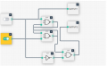
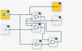
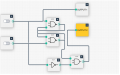
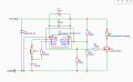
I have designed the following circuit (see attachment): A 555 timer is used as a flip/flop to control a MOSFET.
I want to add a startup and shutdown sound (two different sounds) to this circuit. My question is, what's the easiest way to do this (I have limited space)?
I have designed the following circuit (see attachment): A 555 timer is used as a flip/flop to control a MOSFET.
I want to add a startup and shutdown sound (two different sounds) to this circuit. My question is, what's the easiest way to do this (I have limited space)?
Attachments
-
 97.6 KB Views: 17