 Facebook
 Google
 GitHub
 Linkedin
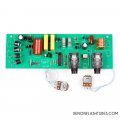
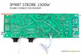
Attached are some fotos and a description of a 220v 1500w Xenon strobe driver that uses direct current from the mains.
The strobe is not sold anymore. The new ones like this do not have many discreet components.
This strobe driver has no capacitors for the flash storage
A little scary circuit I think (I'm not an engineer..) but it is robust and works well with 220v main power.
However, I live in Ecuador and now we are in an energy crises with 12 hour power cuts per day. This is going to last a long time, as there is a hard drought and no hydro capacity left.
I have a 110v solar inverter that will run a 110-220 transformer. I have a good quality 5000watt transformer, with a copper toroidal core. But it is not fast enough to supply the instantaneous power the strobe needs. So, the strobe runs at maybe 1/2 the wattage.
I have a large photo-flash capacitor 2400mf 360wv and probably I could adapt the strobe motherboard so that the transformer could charge the capacitor and then the flash can be at full power.
Can any of you suggest how this would be done (I can solder...)???
Where to solder and the polarities?
Many thanks
Just for info: use the strobe to power a PEMF circuit. Very simple, very effective, low cost. Powerful. I use it every day.
Ali Express sells a more modern version with hardly any discreet components, but it still does not have storage capacity on the board and runs directly off mains
Attachments
-
 78.9 KB Views: 10
 -
 114.2 KB Views: 9
 -
489.9 KB Views: 4
-
 78.9 KB Views: 10
 -
 114.2 KB Views: 9

