Facebook
 Google
 GitHub
 Linkedin
Hi,
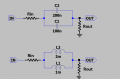
i need help to solve a little doubt. In the image below is wired two inductors and two capacitors with different values. So the question is:
The original circuit it consist in one inductor and one capacitor. The signal pass through this component.
I want to add i a second paralleled inductor or capacitor with different value. When the sinusoidal voltage pass this paralleled components is the signal divided to by the number of paralleled component (in this case two so 50%/50%) or it depend by the value of components (in this case 33% in C1/L1 and 66% on C2/L2) ?
I have to understand if adding the second component in parallel how much signal I remove from the first component.I hope my question is clear. Thanks.
Z
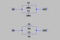
Attachments
-
 7.7 KB Views: 8