AC RLC Circuit Analysis - Trying to pull it all together

Thread Starter

SamR

Joined Mar 19, 2019
5,499
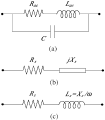
OK so I found out what to do with the resistance of the coil. For Zt it is added to R and for the V across L it and Xl are resolved to find the resultant R across L which is Rl = 95.618Ω * It = 1.378Vl.

But what I am actually measuring is slowly swinging from 750mV to 1.46V over ~1 minute? That is a pretty wide span for the small-signal? I do not know what is happening here and I cannot explain the Vl swing.
 

Thread Starter

SamR

Joined Mar 19, 2019
5,499
I applied a 5kHz LO Pass filter to the scope input and the signal stopped swinging. Not sure where it is coming from but even with probe directly across the Signal Generator w/ 2Vpp @ 300Hz there is noise on the signal. Probably from my computer monitor as it is directly over the signal generator? So now I am getting stable signals from the test circuit.

The measured values reflect the calculated values. I found the source of my confusion! The resistance of the inductor has to be included in the calculations to determine the current for the circuit. And IR is NOT the voltage across the Resistor but rather the entire resistive voltage for the circuit and includes the resistance for the coil. So the measurement across the parallel resistors is the It*R voltage across the resistors only and that calculations voltage agrees with the experimental measurement.

IMG_0513[1].gif

Complex Θ agrees w/ Θ from Vt calculation.

On to LCR...
 

Thread Starter

SamR

Joined Mar 19, 2019
5,499
OK, I did the RLC calcs and built the circuit and took some measurements to compare with my calcs and discovered with further reading that the rest of the exercise is an introduction to Resonance. At 300Hz it is not going to give me what I calculated due to resonance. At this point, I will pull the plug and move on to the resonance chapter and have figured out why my Vr measurements were not what I expected. So it was a good exercise and I learned from it. I have more confidence in my calculations now that the experimental model agrees with the calculated values. Thx for the input guys I really appreciated it.

Sam
 

zmrs17

Joined Aug 17, 2018
1
Hi Sam,

I don't know if you figured out the problem with measuring the phase angle difference between the voltage across the resistor and the voltage across the capacitor in your RC circuit. So, just in case, here's something that you might want to try.

As you probably know, the problem with measuring voltages with a scope is that the scope doesn't have a floating ground. So, if you connect your ground in the middle of a circuit somewhere, say between a resistor and a capacitor, you will short out the component that's tied to ground.

The best way to measure the phase lag between the resistor and a capacitor in the RC circuit is to do this:
1. Set the ground readings for both channels of your scope to mid screen.
2. Connect probe 1 across the entire circuit.
3. Set your time/div scale to display two or three cycles.
4. Connect probe 2 to the component that has one side connected to ground and the other side connected to the other component. This way, both of your probe grounds are connected together.
5. On your scope you will observe the phase difference that you are looking for. Channel 1 will show the phase angle for the entire circuit while channel 2 will show the angle only for the component that you are measuring. Your trigonometry should help you find the remaining angle. Or,
6. You can swap the resistor and the capacitor to see the other phase angle.
7. As you are making your observations, vary the frequency of your signal so you can see the effect that this causes clearly.

You can do the same with an RLC circuit. Just swap the component that is tied to ground with any of the other two that are mid circuit.

Michael Stone
 

MrAl

Joined Jun 17, 2014
13,722
OK, I did the RLC calcs and built the circuit and took some measurements to compare with my calcs and discovered with further reading that the rest of the exercise is an introduction to Resonance. At 300Hz it is not going to give me what I calculated due to resonance. At this point, I will pull the plug and move on to the resonance chapter and have figured out why my Vr measurements were not what I expected. So it was a good exercise and I learned from it. I have more confidence in my calculations now that the experimental model agrees with the calculated values. Thx for the input guys I really appreciated it.

Sam
Hi again,

Very often we have to take into consideration the tolerance of the parts as well as the tolerance of the measuring equipment. If each part could be off by 1 percent and there are three parts, and the measuring device can be off by 1 percent, then the max error could be as high as 4 percent.

This reminds me of the guy who came to our company one time to inspect the equipment we had made for them. He was from what was known as Israeli Aircraft at the time. He wanted voltage measurements using a digital volt meter. The meters back then read just up to a count of 1999 so if the voltage was 120vac it would read just 120.0 and that was as good as you can get. However, what happens a lot is that last digit bounces up and down, so we might see 120.0 and then 120.1 and then 120.0 then 120.1 again.
What he wanted was if we saw that then the reading would get logged as 120.05 which is the average of the two.
An extension of that idea was that if you saw 120.0 for three seconds and 120.1 for one second then the reading would get logged as 120.025 but if you saw 120.0 for one second and 120.1 for three seconds then the reading would get logged as 120.075, and of course if you saw 120.0 for two seconds and 120.1 for one second then the reading would get logged as 120.033 volts, and if 120.0 for one and 120.1 for two then log 120.066 volts.
Pretty interesting dont you think?
It's an interesting lesson in interpreting measurement results.
 

Thread Starter

SamR

Joined Mar 19, 2019
5,499
Thx Al. I was using the measured values of components instead of the rated value to try and reduce error. My acceptable error mark of <5% comes from my days as a chemistry/physics/engineering labs student as that was the target for experimental vs calculated. My bench meter gives good accuracy but unsure as to the LCR meter I have for Henries. The scope seems to truncate measurements (also a bit twitchy due to high sensitivity) and not so accurate. I ended up with an acceptable small error so I can consider the meas vs. calc to be correctly validated.

Sam
 

Thread Starter

SamR

Joined Mar 19, 2019
5,499
What model LCR meter are you using?
An SZBJ BM4040. Goes down to a 200pF range up to 2000uF with a zero adjust and 3 1/2 digits. A 200uH range up to a 20H range and the usual Ω up to 20MΩ plus a continuity tester. You can either use test leads or it has 2 slots to directly insert the component into. I bought because it will test lower than 20pF with the zero adjust which most testers won't (not that I ever use pF caps). How accurate it is??? It has some good reviews and for general use it's fine. It's about the size of my Fluke 83 so I usually grab my little palm-sized TC1 Multi Function Tester chinese special for coils or caps which is handy but probably not super accurate. My Vici 6 digit bench meter will also zero for low capacitance tests but no Henries.
 

The Electrician

Joined Oct 9, 2007
2,986
An SZBJ BM4040. Goes down to a 200pF range up to 2000uF with a zero adjust and 3 1/2 digits. A 200uH range up to a 20H range and the usual Ω up to 20MΩ plus a continuity tester. You can either use test leads or it has 2 slots to directly insert the component into. I bought because it will test lower than 20pF with the zero adjust which most testers won't (not that I ever use pF caps). How accurate it is??? It has some good reviews and for general use it's fine. It's about the size of my Fluke 83 so I usually grab my little palm-sized TC1 Multi Function Tester chinese special for coils or caps which is handy but probably not super accurate. My Vici 6 digit bench meter will also zero for low capacitance tests but no Henries.
Is your BM4040 old enough that it's now obsolete? I can only find the BM4070 with a search on the web.

Would you measure your 33 mH inductor with the meter and monitor the voltage/waveform across the inductor when the meter is making the measurement, showing what the scope measures as the frequency of the applied voltage?
 

Thread Starter

SamR

Joined Mar 19, 2019
5,499
Bump... @The Electrician Never heard back after posting what you asked for?
I can only find the BM4070 with a search on the web.
Ooops typo yes it's the 4070. It reads the coil I grabbed as 32.0mH Raw image/no filtering. I tried the same with the small tester but it does a one-shot test and I'm not sure how to capture and playback on my scope. Something else I need to learn to catch transients.
SDS00005.gif
 
Last edited:
Top