AC RLC Circuit Analysis - Trying to pull it all together

Thread Starter

SamR

Joined Mar 19, 2019
5,052
I have completed the Grob's chapters on reactance and impedance and before I start on resonance I want to try and put it all together so far. I have no one to check my work so if I may impose on you for verification I would very much appreciate it.

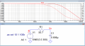
Let me start with a simple capacitive reactance circuit.

Capture.GIF

I am showing the actual measured component values. The 50.7Ω value for R is a pair of parallel 100Ω resistors since I don't have a 50Ω to use. Measuring Vpp across RC on channel 1, Vpp across C on channel 2, and Vrms across R. Signal Generator adjusted for 300Hz @ 2Vpp across RC. And I show my calculated values and my actual measured values. A tiny amount of V across R and almost all across C for a Θ of -85.612° so that looks good. I also put Vr & Vc into Pythagorean's theorem and solved it to find Vt=2.0Vpp which proves correct. The measured Vr is coming from my bench meter after zeroing it for VAC and allowing the measurement to settle.

rc300calc.gif

Now on the scope, I have a bit of noise so I am averaging the reading 256 times to get the values. I am also using the scope to find the phase difference between channel 1 Vt and channel 2 Vc. Am I doing this correctly? I am actually looking to verify my calculation of the phase angle between Vr and Vc? So I suspect this value is incorrect according to my calculations. Is there a way to find this with the scope?

SDSRC300.gif

Thank you for your time and patience with me it is very much appreciated.

Sam
 

Wolframore

Joined Jan 21, 2019
2,610
Sam check your probes are you measuring across Vr? It looks like you’re getting Vt your Vr measurement should be much smaller.
 

ericgibbs

Joined Jan 29, 2010
18,864
hi Sam,
One small point ref LTSpice notation, a Voltage source of 2V is 2Vpeak, so that's 4Vppk. [peak to peak]
You used 2Vpp in your maths, which could be read as 1Vpk [peak] , so 2Vpk would be the correct notation.

E
 

Thread Starter

SamR

Joined Mar 19, 2019
5,052
Thx Wolf. The Vr is being measured by my bench DMM. I also put the scope across the R alone and am measuring 0.184Vpp which also agrees with the DVM and my calculations. I don't seem to be able to measure both the Vr and the Vc due to the probe GNDs? So I cannot get the actual phase between them from the scope?

Thx Eric, the LTS, for now, is just to show the schematic. At this point, I am trying to compare experimental to calculated. LTS analysis comes next. Along with complex rectangular and polar calculations for the ckt.

Sam
 

Wolframore

Joined Jan 21, 2019
2,610
You will need to make a differential measurement using two probes to get Vr to show the correct phase relationship. Do you have an extra channel?
 
Last edited:

Thread Starter

SamR

Joined Mar 19, 2019
5,052
Try setting scope to no averaging, single shot,
Ok Thx. Not sure how to do the single-shot trigger so I'll have to do some trials. What I am seeing is if I place my A probe on n001 and it's GND on n002 and also place B probe on n002 and it's GND on the opposite side of the C it doesn't work due to the probeA GND and probeB placed at the same spot. I can measure across both or one at a time.

Sam
 

Thread Starter

SamR

Joined Mar 19, 2019
5,052
Wolf yes I have 2 channels and PA across R and PB across C gives me this (turned off AVG and turned on HIfilter@5kHz)SDS00009.gif :
 

ericgibbs

Joined Jan 29, 2010
18,864
hi Sam,
This is your circuit in LTS with AC analysis.
Run the sim
Place the cursor on the 300Hz point [dotted plot line] and read the phase shift bottom left hand corner of window.
E
 

Attachments

Thread Starter

SamR

Joined Mar 19, 2019
5,052
-90° - -4.4155873°=~ -85.6° which agrees with my calculations. Still struggling with how to capture this on my scope. The floating GND is interesting but I only have 2 channels. Which is why the exercise was measuring Vt and Vc and assuming Vr was so close to 0 as to be considered nil. Labs were based on using Analog Scopes and reticule measurements. Still learning to use this scope as I keep finding new things as I go along such as measuring phase angle. Spoiled a bit by the Auto Trigger doing a lot of the drudge work of isolating a signal by twisting knobs. So it seems that my experimental values are pretty close to my calculated values within the limitations of my instruments? Haven't gotten into dB measurements yet Eric but it's coming soon in the resonance chapter. OK let me recalculate it all out in complex numbers and see what I come up with next.

Thx guys!
Sam
 

Thread Starter

SamR

Joined Mar 19, 2019
5,052
@Wolframore

Apparently, my Siglent 1102CML+ does not have isolated inputs and Differential Probes are quite pricey so I'm stuck with what I have available. The input seems to drift around a bit and I assume it is some resonance effect? I did find some filtering to smooth it a bit and doing start/stop captures at least give a solid grab as it floats about.

Sam
 

Wolframore

Joined Jan 21, 2019
2,610
@SamR, I have the same issues with my Hantek, I wish I had held off for a 4 channel now that I'm doing more AC analysis. I wonder if someone else knows a way around this.

For now maybe it's best to just simulate. The phase relationship is there and your calculations looked good, I didn't check but your results make sense.
 

Thread Starter

SamR

Joined Mar 19, 2019
5,052
I think so. I didn't do error analysis but they look right to me and make sense. I'll be moving forward to LR and LCR serials but next will do the complex calculations to compare. Just trying to get comfortable with experimental vs. calculated for LCR.

Sam
 

crutschow

Joined Mar 14, 2008
34,459
For low frequencies you could make a simple differential probe using an instrumentation amp IC.
It can directly drive the 1MΩ input of the scope over a short twisted-wire pair (unshielded), or you can connect a probe directly to the output.
It could be powered by two 9V batteries.
 

Thread Starter

SamR

Joined Mar 19, 2019
5,052
So Zt=50.7Ω -j658.543Ω which converts to 660.492∠-85.598°

Which ~= to what I calculated previously for Zt and Θ. So that is much easier.
 

Thread Starter

SamR

Joined Mar 19, 2019
5,052
I appreciate the info on differential probes but I don't think I am ready to tackle that just yet. Working on the RL circuit and need to find out what to do with the inductor's internal resistance. Simply add it to R in the Zt equation? or? What I calculated and am measuring do not agree. Still working on it but I need a lot of breaks along the way to rest my back. That and all the hurricane hoopla going on ATM.
 
Top