AC current sensing (rectify, amplify + levelshift)

Thread Starter

Col

Joined Apr 19, 2012
44
Hi,

I'm designing a circuit to measure AC current flow based on the Allegro ACS714 (Hall effect current sensor -> 100mV/Amp). I want to catch a small current, few 10s to few 100s of mA. Setting 100mA as the design goal => and input signal 10mV. ACS714 output is small signal AC at a 2.5V reference.

I have four goals with my measured signal

1. I would like to gain my signal for effective ADC sampling
2. I would like to rectify the signal for ADC
3. I would like to shift the reference to 0V
4. Reduce amplifier bandwidth to reduce high frequency noise

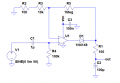
I though this was pretty simple... I AC coupled my signal into an inverting opamp (LMV321 powered with 0-5V) precision rectifier starting with a modest gain of 100. I put a bandwidth reducing cap in the feedback path. I attach a sketch of the circuit.

I built the circuit and my amp output is driving to the positive rail and becomming hot. Am I missing something silly? Ive checked for shorts, diode polarity etc.


chrisw1990

Joined Oct 22, 2011
551
http://forum.allaboutcircuits.com/showthread.php?t=61029
take a look here for making the signal relative to 0V..
i think your amplifier wont like the feedback after the diode, so it will be trying to drive it to make it correct.. think of it like balancing the load almost? put the feedback circuit before the diode and try that..
in order to rectify it, you could try 4 diode rectification, or, a low pass filter maybe.. i know this works with square waves but the harmonics of the sine wave are different. maybe worth a go.
 

chrisw1990

Joined Oct 22, 2011
551
i think the cutoff frequency would have to be very low for the filter to work.. might make it unuseable..
got to be honest, iv never seen an opamp used like that so i dont want to say, yes or no... iv never heard of an opamp being used like that.. id look more into the theory of it first:) maybe theres something youre overlooking :)
 

chrisw1990

Joined Oct 22, 2011
551
ah right yeh maybe.. try that transistor circuit in the thread of the link i posted, iv used it on a board im looking at now.. works quite well:) obviously your components will be different but simulate and try it out:)
 

Ron H

Joined Apr 14, 2005
7,063
Col, you need a negative supply.

EDIT: What are you using to get your +5V? We might be able to get a negative supply from it.

Chris, the circuit you posted here doesn't make any sense. The input signal goes to the power pin of the output amplifier, and the collector of the emitter follower. Also, Col wants a precision circuit. The addition of an emitter follower which is not inside a feedback loop eliminates this possibility.
With all due respect, Chris, you are over your head on this topic. Giving advice when you don't know what you are doing is not helpful.
 
Last edited:

Thread Starter

Col

Joined Apr 19, 2012
44
Thanks Ron... you are right I have been seeing some component of my signal on the supply. Unfortunately dual supply isnt an option in my application. I've thrown out the previous circuit in favour of the much simplified one attached, just a gain amp and a tank filter. I've sacrasfised half my ADCs range plus the diode drop, so really I would hope for a better solution.


I can tolerate losing half my signal before rectification, at least i'd be using more of the ADC range. It there a way to let my amp saturate for the negative half-cycle without all the nasty side effects... perhaps put the diode and capacitor before the amplifier could work...
 

Ron H

Joined Apr 14, 2005
7,063
Thanks Ron... you are right I have been seeing some component of my signal on the supply. Unfortunately dual supply isnt an option in my application. I've thrown out the previous circuit in favour of the much simplified one attached, just a gain amp and a tank filter. I've sacrasfised half my ADCs range plus the diode drop, so really I would hope for a better solution.


I can tolerate losing half my signal before rectification, at least i'd be using more of the ADC range. It there a way to let my amp saturate for the negative half-cycle without all the nasty side effects... perhaps put the diode and capacitor before the amplifier could work...
My comment about signal on supply was directed at Chris's post.
I asked you where your +5V comes from.
 

Thread Starter

Col

Joined Apr 19, 2012
44
Ive got an AC/DC converter from the mains. In my component count critical application, this element is the only analogue part. I'd realy rather not go adding further power devices for voltage inversion
 

chrisw1990

Joined Oct 22, 2011
551
yes sorry the schematic was wrong, and when i put it on pcb, that was all corrected.. for some reason i hadnt connected the power together for the hall sensor and the trannie and opamp. nor outputted the signal.
my direction towards that thread was for removing the dc offset. which was the use of the transistor in the middle.
sorry if you think i am over my head. trying to help a colleague was my aim, and in my eyes i did that by pointing to the thread.
 

Thread Starter

Col

Joined Apr 19, 2012
44
Implementing the simpler circuit... I have a rectified output signal which is offset by a reference of 2.5V. MY microcontroller has a 3.3V supply, (my ADC reference voltage). This is leaving me with a small 0.8V effective signal range... just too little in my opinion.

Ron... is there a way to remove the 2.5V offset from my DC signal? I never really considered I could use opamps for DC signals. Again, putting in negative supply voltage is not an option
 

Ron H

Joined Apr 14, 2005
7,063
Implementing the simpler circuit... I have a rectified output signal which is offset by a reference of 2.5V. MY microcontroller has a 3.3V supply, (my ADC reference voltage). This is leaving me with a small 0.8V effective signal range... just too little in my opinion.

Ron... is there a way to remove the 2.5V offset from my DC signal? I never really considered I could use opamps for DC signals. Again, putting in negative supply voltage is not an option
Are you wanting to digitize the instantaneous half-wave rectified output, or do you want a precision peak rectifier, where the peak value is converted to DC (with a little ripple)?
 

Thread Starter

Col

Joined Apr 19, 2012
44
Is it really bad to just let the amplifier saturate?... since its only 50Hz I dont imagine it would be much affected by the saturated amps recovery time
 
Last edited:

Ron H

Joined Apr 14, 2005
7,063
Here is a circuit that works well in simulation. You should be able to use any op amp whose input and output can go to the negative rail (GND). On most such amps, the input must never exceed -0.3V, although LMV321 is rated at -0.5V max.
I set the gain at 100. You can adjust it as required. Keep in mind that the op amp's input offset voltage will be amplified by the gain. You can't put a cap in series with R2 to reduce the DC gain to 1, because the cap would charge up to the point where the circuit doesn't work.
You can disconnect the input and replace it with a short, then measure the zero-signal output offset voltage.
Keep in mind that the output time constant is about 100 seconds, so sudden large decreases in the input signal will take a long time to show up on the output. You can reduce the output cap at the cost of more ripple.

EDIT: You can do this with a gain of 50 preamp with AC coupling, which will reduce the gain requirement for the rectifier, thereby reducing the output offset. It would require a dual op amp (same approximate footprint), and two more resistors and a 1uF capacitor. Let me know if you're interested.
 

Attachments

Last edited:
Top