 Facebook
 Google
 GitHub
 Linkedin
Hi All,
We are busy with a project that takes measurements from a Current Transformer (CT) to track current usage in attached appliances. The CT is connected through an amplifier circuit to a micro-controller ADC pin. The AC wave (positive cycle only) is sampled at 100us intervals (there are a few channels to sample) and a snapshot of the positive half of a wave is recorded. From this snapshot we hope to calculate the current usage of the attached load.
We understand that in order to get an accurate power reading of the attached load we need to get an RMS current value from the CT, an RMS voltage value of the supply and the power factor (measure the phase angle difference between the supply voltage and load current).
Step 1 is to convert the ADC reading from the CT to a current value that is consistent with a Digital Multimeter (DMM) or within a small margin of error.
We believe that it should be possible to take snapshots (ADC values) of various types of loads with similar current ratings and the calculation employed should yield values that correspond to DMM readings. ie. If the DMM measures 2 different types of 15W loads and sees a current of 69mA and 58mA respectively (ratio of 1.19), then our calculation using ADC values should yield a similar ratio between the 2 loads.
Here are the values recorded for each load, 15W Incandescent and 15W LED lighting. (see graph)
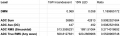
The various measurement strategies yield the following results and ratios: (see table)
Where we calculate these values using the following formulas:
ADC sum = sum of all values
ADC Ave = average of all values
ADC RMS = peak * 0.707
ADC True RMS = Square root of the average of the sum of the squares
As you can see the sum/ave have a similar ratio but in the opposite direction and the RMS / True RMS calculations are way off.
Is the strategy to get the AC current employed here correct or valid?
What is the DMM using (Doesn't say it's a True RMS meter)?
Is the phase angle difference the issue here and do we need it for an accurate current measurement?
What are we missing?
Thank you for any insights.
Mark
We are busy with a project that takes measurements from a Current Transformer (CT) to track current usage in attached appliances. The CT is connected through an amplifier circuit to a micro-controller ADC pin. The AC wave (positive cycle only) is sampled at 100us intervals (there are a few channels to sample) and a snapshot of the positive half of a wave is recorded. From this snapshot we hope to calculate the current usage of the attached load.
We understand that in order to get an accurate power reading of the attached load we need to get an RMS current value from the CT, an RMS voltage value of the supply and the power factor (measure the phase angle difference between the supply voltage and load current).
Step 1 is to convert the ADC reading from the CT to a current value that is consistent with a Digital Multimeter (DMM) or within a small margin of error.
We believe that it should be possible to take snapshots (ADC values) of various types of loads with similar current ratings and the calculation employed should yield values that correspond to DMM readings. ie. If the DMM measures 2 different types of 15W loads and sees a current of 69mA and 58mA respectively (ratio of 1.19), then our calculation using ADC values should yield a similar ratio between the 2 loads.
Here are the values recorded for each load, 15W Incandescent and 15W LED lighting. (see graph)
The various measurement strategies yield the following results and ratios: (see table)
Where we calculate these values using the following formulas:
ADC sum = sum of all values
ADC Ave = average of all values
ADC RMS = peak * 0.707
ADC True RMS = Square root of the average of the sum of the squares
As you can see the sum/ave have a similar ratio but in the opposite direction and the RMS / True RMS calculations are way off.
Is the strategy to get the AC current employed here correct or valid?
What is the DMM using (Doesn't say it's a True RMS meter)?
Is the phase angle difference the issue here and do we need it for an accurate current measurement?
What are we missing?
Thank you for any insights.
Mark
Attachments
-
 67.5 KB Views: 14
 -
 63.7 KB Views: 14


