I thought I did that... did you see the zip file containing the pictures? They're as close up as my camera can get. If you need closer... then I can do that after Christmas when my wife opens her gift
I wonder if making these cables would have a market, or if a camera USB to vid/audio cable is the same. My Fujifilm output is oval micro USB looking connector, but with 7 pins.
There must be a camera out there that uses the mini 5 for output, maybe Kodak or Samsung? Who owns motorola, or what other companies does Motorola own? That might lead us to who might make the cable that works with their cameras. Maybe check out what the sony ones look like. Both Still picture/small video and full fledged video cameras with still picture ability by all brands. I'm positive one is out there, Maybe even the Motorola Razr headphone adapter would be what you want. Not the new Razor, but the thin Razr from 4 years ago.
I'm in the same boat as the OP. I've tried a four ping usb cable from Summer and all I got was audio. I'm wondering if Motorola is doing this on purpose because the output does not work or perhaps its PAL ?
I did a little more digging and Motorola's call center had received MANY calls regarding this and has been given NO information. I took the unit apart again and started probing with my meter. Of the 5 pins, 1 does nothing (its soldered to the board, but the short trace goes to an unpopulated pad for a resistor or capacitor or something - but since nothing's there, its essentially not connected), 1 is 3.3v power and 1 is ground. I don't know what the other two are. Is there any need for 3.3v power in an a/v setup though? That either concerned me that this is in fact a data port and not a/v as marked... or maybe the power is used as a signal switch? Perhaps the non existent cable shorts the power (to ground?) flipping a transistor to shut off the screen and turn on the a/v output?
I took as detailed photos of the circuit board as I could, but I honestly don't think they're any better than what I've already posted (in the zip file, obviously, not the very low-res image files) and the only response I got to that was some obscure language reference of the word "really".
Note that I accidentally briefly shorted the 3.3v and ground while the unit was powered. The screen briefly turned off and the audio went dead - it came on momentarily after I corrected the short. Is that evidence of what I proposed in the previous paragraph? Or is that simply that I nearly ****ed up my unit and caused it to "reboot"?
Note that I accidentally briefly shorted the 3.3v and ground while the unit was powered. The screen briefly turned off and the audio went dead - it came on momentarily after I corrected the short. Is that evidence of what I proposed in the previous paragraph? Or is that simply that I nearly ****ed up my unit and caused it to "reboot"?
Most likely the latter. The ports are supposed to be current limiting but they usually use a fuse instead. If it still works and there is still voltage there, you shouldn't of hurt anything if it was ground you hit (and not the audio/video pin).
If your meter is on AC, do you get any reading between ground and the two "other" pins? One could be composite video and show some voltage if your meter has enough bandwidth, the other would be mono/single-channel audio, and would show voltage when a sound is made, again, if your meter has a high enough bandwidth.
Put it on AC mV and see if it gives a reading other than the disconnected value.
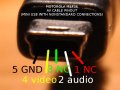
Hi all. I just come from visiting a friend who has one of these baby monitors. We were able to get audio output, but no video at all. Here you have the pinout, which could be useful:
Signal ground.
AV cable connection sense.
??? (most probably this is either unconnected or the video signal).
Audio signal.
??? (most probably this is either unconnected or the video signal).
Pins are numbered from right to left when you look at the plug with the pins on top.
Now about the famous 3.3 V line. You are safe: we found out that serves to sense when the AV cable is plugged in order to turn off the screen and the speaker:
[...]Of the 5 pins, 1 does nothing [...], 1 is 3.3v power and 1 is ground. [...] Note that I accidentally briefly shorted the 3.3v and ground while the unit was powered. The screen briefly turned off and the audio went dead - it came on momentarily after I corrected the short. Is that evidence of what I proposed in the previous paragraph? Or is that simply that I nearly ****ed up my unit and caused it to "reboot"?
Pin 2, which is the one connected to 3.3 V, is actually a digital input which turns off the screen and the speaker when pulled to ground. The 3.3 V are maintained when unconnected by a pull-up resistor of roughly 20 kΩ so that the gate voltage is not floating freely, by the way; we put a 18 kΩ resistor between pin 2 and pin 1 and the voltage on pin 2 fell to about 1.5 V and we also measured the current between pin 1 and pin 2 when shorted and it was of something between 0.1 mA and 0.2 mA. When you shorted this pin to ground, you disconnected the screen and the speaker, but that's the expected behaviour. Note that we got audio output through pin 4 both with pin 2 connected to ground and disconnected (in which case we got audio both on TV and on the monitor device).
So this is what we know so far: you must connect pin 4 to the audio signal cable (inner pin of the RCA connector), pin 1 to signal ground and finally pin 2 to pin 1 if you want the screen and the speaker to be turned off when you plug the cable. We still have to discover what strange thing is happening to the video signal.
I hope this helps. I'm sorry that we could not get any video.
Excellent news! My friend kept tinkering and found the right connections. Here's the final pinout (numbered right to left when looking towards the plug with the pins on top):
Ground.
Audio.
Perhaps nothing.
Video and plug sensor.
Perhaps nothing.
(note that I mixed up pins #2 and #4 in my previous response)
The plug sensor is coupled to the same pin as the video signal. There must be some low-pass filter between the digital gate of the plug sensor and the pin so that the video signal does not trigger the detection of pluggin and unplugging.
Mini USB cables have a colour code for the signal and power wires. They usually have a black wire connected to pin 1 (ground), a white wire connected to pin 2 (data -) and whatever connected to pin 4 (ID, which is either grounded or left floating). There are no yellow wires as far as I have seen, so they chose the only undefined wire and connected it to the signal pin of the yellow RCA plug (video); the black wire goes to ground (as usual) and the white wire goes to the signal pin of the white RCA plug (audio). It makes sense.
In few words: connect the signal wire (inner wire which goes to the inner pin of the plug) of the white RCA cable (audio) to mini USB pin 2, the signal wire (inner wire which goes to the inner pin of the plug) of the yellow RCA cable (video) to mini USB pin 4 and the ground shield (outer shield of the cables which goes to the outer rings of the plugs) to mini USB pin 1.
Way to go! Now to be absolutely clear, do you think you could upload a diagram? I'm not sure I exactly follow "when looking towards the plug with the pins on top". Its ambiguous as I'm not sure what the "plug" is (usually that's the bit at the end of the cable, but I think you mean the header?) and I'm also not sure exactly what you mean by "pins on top" if you are talking about the header.
If you can't upload a drawing, then fill in the blank (because I think this is a more clear way to word it):
"When holding the device so you're looking at the AV OUT recepticle and the lettering is upright... pin #1 is the pin on the ______. "
I mixed up the pinout again, but now it seems that I got it right. When holding the device so you're looking at the AV OUT recepticle and the lettering is upright, pin #1 is the pin on the left. When holding the mini USB connector so you're looking at the plug (not cable) side and the wider side of the outer metal sleeve is on top, pin 1 is on the right. The pinout, from pin 1 to pin 5, is the following one:
Not connected.
Audio (white).
Not connected.
Video (yellow).
Ground (black).
See the attachment for a photograph of a mini USB plug showing the pins.
This is great, so does anyone know if a pre-made cable that will work with this pin configuration, or is the only hope to hack up some radio shack cables together?
I did find one place that had no stock but it had the exact same pinout. It said it was for something like "custom av". They were $15 plus shipping from Canada. I emailed them about when they'd get stock and they said they make them as needed. I'm waiting for more clarification. Hmmm... I'd post a link but I can't seem to find it at the moment. When I get home I'm sure I have it bookmarked.
You seem to have the issue solved. Sometimes you can find some useful information by looking up the FCC ID #. The manufacturer has to submit a substantial file of information to get their device certified.
I believe the next problem your going to realize/run into is that in all "normal" USB data/charging cables, the pin used for video here is not normally connected to anything, thus it is not connected to a wire in the cable, thus you can't just buy any old cable with a mini USB end and cut it hoping to attach your own RCA jacks...
2) miniUSB to an analog video capture "dongle" that would connect to a computer via USB (then you could record the feed with Vitamin D video, some other DVR software, or stream it over the Internet with webcamXP or similar)
 Facebook
 Google
 GitHub
 Linkedin
")