A Relay setup to run a sequence of device states

dcbingaman

Joined Jun 30, 2021
1,065
Don't give up! I think we are close! I will work some more on the pdf documents. It might be feasible, but take a little more work. Remember we also have one SPDT relay left since you only have 3 devices to control. I will work some more on trying to figure it out. :)
 

dcbingaman

Joined Jun 30, 2021
1,065
Thanks for this but as there are three devices (batteries) I don't think this will work. I think your suggestion would work with just one battery rotating around three states but I'm not sure about it working for what I am actually trying to achieve.
Actually I think it can work with the three batteries also the people on the forum have offered a lot of good options. I don't think a solution is far away at this point.
 

crutschow

Joined Mar 14, 2008
38,669
After a little further though, I realize you don't need steering diodes if using 6 relays.
Each state has two relays energized just once per cycle, so just connect the relay driver (3 needed, could be NPN emitter followers) from each of the three counter outputs to the two relays energized for each state.
 

dcbingaman

Joined Jun 30, 2021
1,065
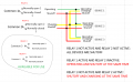
I have not worked out all the details yet, but the following picture (brainstorming) is what I have come up with so far:

1695668163725.png
We have not achieved the entire goal but there is only 2 relays being used. I think we can find a way to use the other two relays to accomplish the goal.

I am concerning myself with the 'electronics' side after I have this done. As we still need some sort of timer circuit and probably some diodes for charging/discharging.

I will work on this diagram some more either later today or tomorrow.
 

Thread Starter

Tutor88

Joined Feb 8, 2023
306
I have not worked out all the details yet, but the following picture (brainstorming) is what I have come up with so far:

View attachment 303469
We have not achieved the entire goal but there is only 2 relays being used. I think we can find a way to use the other two relays to accomplish the goal.

I am concerning myself with the 'electronics' side after I have this done. As we still need some sort of timer circuit and probably some diodes for charging/discharging.

I will work on this diagram some more either later today or tomorrow.
All looks very promising. I had posted earlier (post 11) a part schematic with the timer circuit and Johnson decade counter.
 

BobTPH

Joined Jun 5, 2013
11,609
Seems like another good plan, and with fewer relays. I will try and draw up both options.
It is not fewer relays. you still need another relay to activate the shutoff state.

And my solution, with a simpler, SPST relay wiring, also guaranteed there would be no overlap and required another relay for the shutoff.

I see no advantage of @MrChips solution over mine, as long as the the situation is as you described, with both the run state and the charge state sharing a common connection to the battery plus. If the two switches needed to be isolated, there the DPDT solution can handle it and mine cannot.

Do you understand that a single relay does not have three states, and therefore cannot do what you want?
 
Last edited:

MisterBill2

Joined Jan 23, 2018
27,977
Is there any problem with a bit of overlap between charge and run states on a battery powered system? Or does the specification forbid it?? In some "real world" systems it is allowed, while in others it is not allowed.
Consider also that it could be accomplished by either a ring counter for each device package or a ring counter for advancing which package is in which state. There are probably advantages to each scheme.
 

Thread Starter

Tutor88

Joined Feb 8, 2023
306
In the real world, and being practical, a small overlap is ok, especially if introducing a ‘Dead band’ makes the design that much more complicated.
So is there a consensus that BobTPH’s idea is the most elegant and simple? Or DCBingaman’s, or another, as I don’t really want to be trying to draw up two or three different designs.

Can I get away with 3/4 SPDT relays if some overlap is ok?

:oops:
 

crutschow

Joined Mar 14, 2008
38,669
Can I get away with 3/4 SPDT relays if some overlap is ok?
I don't think so.
I believe all schemes will need two relays per Device, since you have three states per Device.

Two SPDT relays eliminate overlap, but require diode steering logic (or other logic) to operate the relays in proper sequence.

The scheme I proposed uses two DPDT relays which also eliminate overlap, but require no steering diodes.

Take your pick.
 

eetech00

Joined Jun 8, 2013
4,723
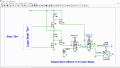
I think this is the relay circuit idea BobTPH offered.
I put in the mosfet driver thinking the state logic would be built using CMOS logic devices.
The circuit is shown in the power-off state (no power applied).

1695715068634.png
 

Thread Starter

Tutor88

Joined Feb 8, 2023
306
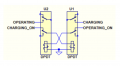
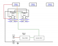
Ok, here is a first attempt at piecing it together and I have only done the first pair of DPDT relays for one device based on Crutschow's design, which appears to have similarities with others.

This is based on his relay schematic below, although this appears to show the 'Charging On' and the 'Operating On' at the same time which is not supposed to happen for a single device.

That issue aside for the moment, regarding how it moves on to the next state; when a high comes from 'Counter 417', it flips both Relay 1 and 2 to their other poles, and I assume that this trigger pulse will also be fed to the other two sets of relays to flip them simultaneously. They will need to be wired up so that no two devices are in the same state at the same time.

On the right track?

DPDT Relays.png


First relay draft.png
 

Thread Starter

Tutor88

Joined Feb 8, 2023
306
I think this is the relay circuit idea BobTPH offered.
I put in the mosfet driver thinking the state logic would be built using CMOS logic devices.
The circuit is shown in the power-off state (no power applied).

View attachment 303493
Looks interesting too, but for my sanity, I will go down the above route and then look at the electronic components later when I get to assemble the actual schematic for a PCB. The above 'Drive Block' schematic is required for each device?
 
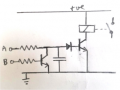
I'm hesitating to make a contribution after all the ideas that come before, but I think that post #11 clearly shows how the 4017 can rotate through three output states and if you use six relays the only remaining issue is how to make sure that each relay turns off (open circuit) before the next one tums on. So given the first output "A" turns the relay on, the next output "B" needs to turn that relay off before turning its relay on. So how about:
1695730510727.png
So when A goes high it turns the transistor on but there is a delay until the capacitor is sufficiently charged. When B goes high it discharges the capacitor so the relay turns off quickly and turns its own relay on after a delay. It may be an issue if high current is being switched to have the relay turn on and off slowly so an arrangement with a comparator may be necessary. I'm actually not sure the diode is necessary or even adviseable.
 

AnalogKid

Joined Aug 1, 2013
12,232
This is based on his relay schematic below, although this appears to show the 'Charging On' and the 'Operating On' at the same time which is not supposed to happen for a single device.

That issue aside for the moment, regarding how it moves on to the next state; when a high comes from 'Counter 417', it flips both Relay 1 and 2 to their other poles, and I assume that this trigger pulse will also be fed to the other two sets of relays to flip them simultaneously. They will need to be wired up so that no two devices are in the same state at the same time.

On the right track?

View attachment 303496
Not quite. Charging On and Operating On are signals from two different outputs of the 4017.

Charging and Operating are the two power sources that are being switched to the devices. He did not show the device connection. I think it is connected to the two upper armature terminals.

According to your chart in post #1, each state (4017 output) energizes one charging output and one operating output. With six individual SPST relays, you can tie the appropriate coils together to each of the three relay drivers. The possible issue is that relays tend to release more slowly than they activate. This is why there is a chance of cross-conduction. The relay arrangement eliminates this chance, but increases the relays to DPDT. At high power levels, this might be a significant cost increase. So, steering diodes and more contacts versus possible cross-conduction.

ak
 

BobTPH

Joined Jun 5, 2013
11,609
I think this is the relay circuit idea BobTPH offered.
I put in the mosfet driver thinking the state logic would be built using CMOS logic devices.
The circuit is shown in the power-off state (no power applied).

View attachment 303493
Yep, that is the idea.

You can do this entire thing with two relays with enough poles. I will leave it as an exercise, since no one (@eetech00 excepted) seems to listen to me anyway
 
Top