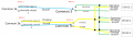
A Relay setup to run a sequence of device states

Thread Starter

Tutor88

Joined Feb 8, 2023
306
Not quite. Charging On and Operating On are signals from two different outputs of the 4017.

Charging and Operating are the two power sources that are being switched to the devices. He did not show the device connection. I think it is connected to the two upper armature terminals.

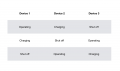
According to your chart in post #1, each state (4017 output) energizes one charging output and one operating output. With six individual SPST relays, you can tie the appropriate coils together to each of the three relay drivers. The possible issue is that relays tend to release more slowly than they activate. This is why there is a chance of cross-conduction. The relay arrangement eliminates this chance, but increases the relays to DPDT. At high power levels, this might be a significant cost increase. So, steering diodes and more contacts versus possible cross-conduction.

ak
Cross over is not a problem for a brief moment I reckon.
 

crutschow

Joined Mar 14, 2008
38,672
this appears to show the 'Charging On' and the 'Operating On' at the same time which is not supposed to happen for a single device.
No.
Look at the path for the relay coil voltage.
If one is on, the coil path for the other is open through the NC contact.

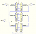
Below is the basic connections for the 3 Devices.
The transistors drive the relay coils from the counter output.
The 3 states are from top to bottom in your chart.
1695737714714.png1695737143676.png
 

eetech00

Joined Jun 8, 2013
4,723
Looks interesting too, but for my sanity, I will go down the above route and then look at the electronic components later when I get to assemble the actual schematic for a PCB. The above 'Drive Block' schematic is required for each device?
Clearly, in my opinion, the suggestion by BobTPH, and that I've shown in post #55, is the solution.

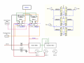
The complete circuit would use three of these blocks (one for each logic state). State "Qn" could be from the output of a CD4017 clocked with 555 timer. The dotted "Logic state Qn" block could be combinational logic that activates its outputs only for its input state, and would be interlocked with the logic of the other two states. The CMOS outputs can't provide enough output current, so the mostfets provide the drive current needed by the relays.
 

Thread Starter

Tutor88

Joined Feb 8, 2023
306
Happy with DPDT as that appears to reduce extra components. This drawing uses two of the outputs from the Johnson counter. Not sure yet where the third goes.

The timer and counter are run by a separate 12V supply. The 'operating' output has its own socket and so does the 'charging' input. Presumably, these can be shared with the other devices.

I am unclear how the two relay coils connect up as surely you can't use one end of a coil to flip the contacts as Crutschow's relay diagram showed. The coils have their own + and - and when energized the contacts swap over.

It would be helpful if someone could screengrab this and then draw on it by hand or otherwise and repost it with all the corrected connections required to run just one device. Then I can replicate it for the other two devices and so on to build up a complete module.

While I'm sure there are subtle electronic improvements to be made, here I am just sorting out what connects with what for the relays, the devices and the timer/counter.

Thanks
 

Thread Starter

Tutor88

Joined Feb 8, 2023
306
No.
Look at the path for the relay coil voltage.
If one is on, the coil path for the other is open through the NC contact.

Below is the basic connections for the 3 Devices.
The transistors drive the relay coils from the counter output.
The 3 states are from top to bottom in your chart.
View attachment 303518View attachment 303517
Ok, thanks but I'm still confused by your yelloow relay diagram. The transistors appear to be driving the relay contacts whereas I thought the coils caused them to flip and so all inputs had to go to the coils?
 

crutschow

Joined Mar 14, 2008
38,672
This drawing uses two of the outputs from the Johnson counter.
If you are referring to my post #63 drawing, there are three transistors for the three counter outputs.
The transistors appear to be driving the relay contacts whereas I thought the coils caused them to flip and so all inputs had to go to the coils?
What do you mean "driving the relay contacts"?
Do you not understand how relay contacts work?
The voltage from the transistor emitter goes through the NC (closed) contacts to drive the coil on the opposite relay coil, with the other end of the coil going to the common/ground connection, making a complete circuit to drive the coil.
 

BobTPH

Joined Jun 5, 2013
11,609
If you are referring to my post #63 drawing, there are three transistors for the three counter outputs.
What do you mean "driving the relay contacts"?
Do you not understand how relay contacts work?
The voltage from the transistor emitter goes through the NC (closed) contacts to drive the coil on the opposite relay coil, with the other end of the coil going to the common/ground connection, making a complete circuit to drive the coil.
But why the cross coupled relay coils when a simple SPDT is just as good at preventing overlap? When the battery is connected to the charger via one of the NC or NO contacts, and to the load through the other, there can be no
overlap.
 

Thread Starter

Tutor88

Joined Feb 8, 2023
306
But why the cross coupled relay coils when a simple SPDT is just as good at preventing overlap? When the battery is connected to the charger via one of the NC or NO contacts, and to the load through the other, there can be no
overlap.
I get the way the coils are energized now, via a closed contact. I'm used to them being energized straight across the coils. I will draw it up and post in the morning.
 

crutschow

Joined Mar 14, 2008
38,672
But why the cross coupled relay coils when a simple SPDT is just as good at preventing overlap?
Not better, just simpler.
It would appear that the SPDT approach requires logic gates/diodes from the counter to energize the relays in proper sequence (have you looked at that).
The cross-coupled relays don't, as you can see in post #62.
So it's a trade-off between SPST relays with added logic, or DPDT relays requiring none.

Your choice.
 
Last edited:

Thread Starter

Tutor88

Joined Feb 8, 2023
306
Not better, just simpler.
It would appear that the SPDT approach requires logic gates/diodes from the counter to energize the relays in proper sequence (have you looked at that).
The cross-coupled relays don't, as you can see in post #62.
So it's a trade-off between SPST relays added with logic, or DPDT relays requiring none.

Your choice.
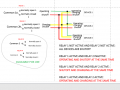
I have attempted to draw up your design using DPDTs but am not fully clear on where the power in and out goes on the contacts. Please have a look and correct as required. I'm also confused by the labels 'operating', 'charging on' etc. For example, on the top left of your relay diagram, you have 'charging on' connected to Q1. So is the charging power coming through Q1?

Relay Draft 3.png
 

BobTPH

Joined Jun 5, 2013
11,609
Okay, I missed that. Mine requires two transistors per device, your required 3 transistors for all.
 
Last edited:

crutschow

Joined Mar 14, 2008
38,672
t am not fully clear on where the power in and out goes on the contacts
you have 'charging on' connected to Q1. So is the charging power coming through Q1?
No.
"Charging_on" and "Operating_on" are the respective control signals to the relay coils.
The transistor collectors go to your plus supply voltage.

"Charging" and "Operating" go to the respective Devices' charging and operating circuits.

There are no "Off" control signals as you show, which makes your schematic confusing.
You can call them 'In" or "Out" if that helps your understanding.

Make sense?
 
Last edited:

dcbingaman

Joined Jun 30, 2021
1,065
In the real world, and being practical, a small overlap is ok, especially if introducing a ‘Dead band’ makes the design that much more complicated.
So is there a consensus that BobTPH’s idea is the most elegant and simple? Or DCBingaman’s, or another, as I don’t really want to be trying to draw up two or three different designs.

Can I get away with 3/4 SPDT relays if some overlap is ok?

:oops:
We have a lot of good people on this forum that can help. It probably is a combination of things from BobTPH’s idea, and others combined with what I am proposing. I will try to work on the drawing some more to see if it is feasible.
 

dcbingaman

Joined Jun 30, 2021
1,065
We have a lot of good people on this forum that can help. It probably is a combination of things from BobTPH’s idea, and others combined with what I am proposing. I will try to work on the drawing some more to see if it is feasible.
For the following diagram:

1695760945272.png

All three can be 'Operating'. All three can be Charging and all three can be Shutoff. The question is do you want this behavior or would you prefer a situation where each device could be in each state (individually)? I am still working with the remaining 2 relays to try to solve the latter.
 

Thread Starter

Tutor88

Joined Feb 8, 2023
306
For the following diagram:

View attachment 303556

All three can be 'Operating'. All three can be Charging and all three can be Shutoff. The question is do you want this behavior or would you prefer a situation where each device could be in each state (individually)? I am still working with the remaining 2 relays to try to solve the latter.
As the table in post 1 shows none of the three devices is in the state of any of the others so each device is in a unique state and they rotate round. This is what the relay layout in post 72 does and which I’m focusing on.
 

dcbingaman

Joined Jun 30, 2021
1,065
For the following diagram:

View attachment 303556

All three can be 'Operating'. All three can be Charging and all three can be Shutoff. The question is do you want this behavior or would you prefer a situation where each device could be in each state (individually)? I am still working with the remaining 2 relays to try to solve the latter.
I think for the latter this should work. But I need to clean it up some.
1695763795918.png
 

crutschow

Joined Mar 14, 2008
38,672
Note that, depending upon the coil-current of the relay type selected, it may be better to use a higher current transistor in my circuit (e.g. 2N2222) in place of the 2N3904s.
 
Top