A Relay setup to run a sequence of device states

Thread Starter

Tutor88

Joined Feb 8, 2023
306
n

No, you misunderstand my question.

Each state of the device requires some set of connections. You have not told us what those are, and we cannot determine that from what you have said. You question was about how to sequence it. My question is: sequence what?

A valid answer might be:

1. Running: Connect 12V to the red wire only.
2. Charging: Connect 12V to the blue wire only.
3. Idle: No power connected.

This would require two relays per device.
I haven’t figured all that out yet but, to give an example off the top of my head with using a battery: in the ‘operating’ mode the battery will be powering a 10W light; in the ‘charging’ mode it will be receiving about 14V DC from a mains charger, and in ‘shut off’ mode it will be doing nothing. Is that what you mean?

The reason why I’m not going down the microprocessor route is so I can also show it to one of my students and clearly point out the different functions being carried out by each section of the circuit. You can’t do that pointing to a monolithic processor chip.
 

dcbingaman

Joined Jun 30, 2021
1,065
I don't have all the details worked out yet. Ladder logic is strange. :)

But here is a start:

1695561364529.png
The picture is hard to read. I will try to improve it later today when I have time.
 

Thread Starter

Tutor88

Joined Feb 8, 2023
306
I don't have all the details worked out yet. Ladder logic is strange. :)

But here is a start:

View attachment 303402
The picture is hard to read. I will try to improve it later today when I have time.
Thank you. Yes can’t quite read that but I’m sure you’re on the right track. This so-called ‘ladder logic’ seems ideally suited to a hardwired relay-based control system without getting too involved in a programming language.
 
Last edited:

dcbingaman

Joined Jun 30, 2021
1,065
I haven’t figured all that out yet but, to give an example off the top of my head with using a battery: in the ‘operating’ mode the battery will be powering a 10W light; in the ‘charging’ mode it will be receiving about 14V DC from a mains charger, and in ‘shut off’ mode it will be doing nothing. Is that what you mean?

The reason why I’m not going down the microprocessor route is so I can also show it to one of my students and clearly point out the different functions being carried out by each section of the circuit. You can’t do that pointing to a monolithic processor chip.
BobTPH said:

1. Running: Connect 12V to the red wire only.
2. Charging: Connect 12V to the blue wire only.
3. Idle: No power connected.

I think he is on to something there, which is what you want, if you combine that idea with ladder logic. You probably can get it working. I have not worked with Ladder Logic for a long time, so I am trying to figure it out myself from Wikipedia.
 

Thread Starter

Tutor88

Joined Feb 8, 2023
306
BobTPH said:

1. Running: Connect 12V to the red wire only.
2. Charging: Connect 12V to the blue wire only.
3. Idle: No power connected.

I think he is on to something there, which is what you want, if you combine that idea with ladder logic. You probably can get it working. I have not worked with Ladder Logic for a long time, so I am trying to figure it out myself from Wikipedia.
How do these red and blue wires fit into the picture? Are they the mains input Live and Neutral on the top left of my schematic?
 

BobTPH

Joined Jun 5, 2013
11,593
How do these red and blue wires fit into the picture? Are they the mains input Live and Neutral on the top left of my schematic?
That was an example! You have told us nothing about your wiring, which was exactly my point.

Now you have told us:

In operating mode the battery is connected to the load (makes sense).

In charge mode the battery is not connected to the load and is connected to the charging voltage (makes sense).

In shut off mode the battery is connected to nothing (obvious).

So you need two relays to do this. I would use an SPDT relay to switch the battery between the load and the charger, and another relay to disconnect the battery completely.

So, the battery terminal goes to the on/off relay.

The output of that goes to the COM terminal of the SPDT relay.

The NC terminal of the SPDT relay goes to the load

The NO terminal of the SPDT relay goes to the charger.

All the negatives connect together.
 

Thread Starter

Tutor88

Joined Feb 8, 2023
306
That was an example! You have told us nothing about your wiring, which was exactly my point.

Now you have told us:

In operating mode the battery is connected to the load (makes sense).

In charge mode the battery is not connected to the load and is connected to the charging voltage (makes sense).

In shut off mode the battery is connected to nothing (obvious).

So you need two relays to do this. I would use an SPDT relay to switch the battery between the load and the charger, and another relay to disconnect the battery completely.

So, the battery terminal goes to the on/off relay.

The output of that goes to the COM terminal of the SPDT relay.

The NC terminal of the SPDT relay goes to the load

The NO terminal of the SPDT relay goes to the charger.

All the negatives connect together.
I will add to my drawing tomorrow and post for feedback that I have it right. Would this arrangement constitute ‘ladder logic’?

And will this cycle round those three states switching with each of the 4060 output pulses?

What about setting the starting position, for example device 2 to be operating when that is not the next natural progression. A push button putting 12v on the 4060output would simulate a switch event so I imagine would work.
 

dcbingaman

Joined Jun 30, 2021
1,065
Here is the start of an Idea. It is a PDF I started putting together, but is taking longer than expected. Hopefully this will help and yes it is a feedback loop with no 'end'. It sound like you are using it for AC loads, if so, the scheme is the same. I will work on it some more later.

I would also highly recommend reading this from Wikipedia:

https://en.wikipedia.org/wiki/Ladder_logic
 

Attachments

Last edited:

dcbingaman

Joined Jun 30, 2021
1,065
Here is the start of an Idea. It is a PDF I started putting together, but is taking longer than expected. Hopefully this will help and yes it is a feedback loop with no 'end'. It sounds like you are using it for AC loads, if so, the scheme is the same. I will work on it some more later.

I would also highly recommend reading this from Wikipedia:

https://en.wikipedia.org/wiki/Ladder_logic
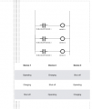
I noticed you need SPTP (Single Pole Triple Throw) switches as you have 3 Devices from the picture each with 3 states (Operating, Charging, Shut-Off):

1695608394645.png
The problem is the device has 4 SPDT (Single Pole Double Throw) switches. But we do have one additional SPDT switch because you are only controlling 3 devices.

I still think we can work out a solution using relays and external timers.

It will take me some more time though to create a schematic showing that.
 

BobTPH

Joined Jun 5, 2013
11,593
I will add to my drawing tomorrow and post for feedback that I have it right. Would this arrangement constitute ‘ladder logic’?

And will this cycle round those three states switching with each of the 4060 output pulses?

What about setting the starting position, for example device 2 to be operating when that is not the next natural progression. A push button putting 12v on the 4060output would simulate a switch event so I imagine would work.
I give up.

There is nothing in my post having anything to do with ladder logic or the sequencing. I was just stating how the relays might be set up.
 

AnalogKid

Joined Aug 1, 2013
12,210
That is the basis of my post - how to achieve the rotation of states shown in the table in post 1 using relays that are either one way or another.
Based on what we know so far, it sounds "one way or the other" will not work. It's more like this-or-nothing, or that-or-nothing, or neither. That would take 6 SPST relays, two per device. Cheap ebay relay modules cannot switch 10 A DC reliably, so that is an issue others can recommend. Once you have a relay part number, the datasheet will dictate the size and type of relay driver.

ak
 

Thread Starter

Tutor88

Joined Feb 8, 2023
306
Based on what we know so far, it sounds "one way or the other" will not work. It's more like this-or-nothing, or that-or-nothing, or neither. That would take 6 SPST relays, two per device. Cheap ebay relay modules cannot switch 10 A DC reliably, so that is an issue others can recommend. Once you have a relay part number, the datasheet will dictate the size and type of relay driver.

ak
Based on the various contributions I will first draw up a ‘flow chart’ rather than a detailed schematic. The logic is the challenge it seems and the tech side is straightforward once that is resolved.
 

Thread Starter

Tutor88

Joined Feb 8, 2023
306
That was an example! You have told us nothing about your wiring, which was exactly my point.

Now you have told us:

In operating mode the battery is connected to the load (makes sense).

In charge mode the battery is not connected to the load and is connected to the charging voltage (makes sense).

In shut off mode the battery is connected to nothing (obvious).

So you need two relays to do this. I would use an SPDT relay to switch the battery between the load and the charger, and another relay to disconnect the battery completely.

So, the battery terminal goes to the on/off relay.

The output of that goes to the COM terminal of the SPDT relay.

The NC terminal of the SPDT relay goes to the load

The NO terminal of the SPDT relay goes to the charger.

All the negatives connect together.
Thanks for this but as there are three devices (batteries) I don't think this will work. I think your suggestion would work with just one battery rotating around three states but I'm not sure about it working for what I am actually trying to achieve.
 

Thread Starter

Tutor88

Joined Feb 8, 2023
306
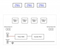
Here is my start to this circuit and I'm using a flow diagram approach rather than the more detailed schematic. Once the main connections between components are sorted then I can complete the schematic for a PCB.

I have included 4 relays in case I decide to use the 'made in China' Wi-Fi-based board that has 4 x 10A capacity relays and can be operated from an app. But that refinement aside, the diagram here can be copied and drawn on with various wiring suggestions.

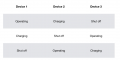
DCBingaman's pdf seems to align with a plausible working option and which uses all 4 relays. I have included the original 'truth' table again to assist.


Relay Circuit 1.png

Sequence table.jpeg
 

MisterBill2

Joined Jan 23, 2018
27,874
One simple? way to implement that state machine sequence with electromechanical relays would be to use a multi-pole stepping relay and a timer, unless each device has an output to indicate that it has completed the charging cycle. This is back to the 1960's technology, though.
Implementing with relays is probably possible, and 4 pole double throw relays are very common and easily available, but not at some hardware stores or hobby shops.
But if this is for a teaching example, then each device can have a contact that changes state when charging is completed. That makes it convenient to design without a timer. REally though, if the sequence is time based, it can be implemented using three standard timers having DPDT contacts and operating on "apply of power".
 

MisterBill2

Joined Jan 23, 2018
27,874
One simple? way to implement that state machine sequence with electromechanical relays would be to use a multi-pole stepping relay and a timer, unless each device has an output to indicate that it has completed the charging cycle. This is back to the 1960's technology, though.
 

AnalogKid

Joined Aug 1, 2013
12,210
To prevent cross-conduction, you need a separate Charge and Operate relay for each device. That's six SPST relays. There are two possible ON states for each device (Charge and Operate) and three steps in the cycle, so that is 6 steering diodes.

Since no relay is on for two sequential events, a single relay power switch, such as a PNP transistor, can kill power to all relays briefly at each event transition.

1 - clock source circuit
6 - power relays
1 - CD4017 configured as a 3-step counter
6 - diodes, 1N914 / 1N4148
3 - NPN relay driver transistors
1 - R-C differentiator
1 - PNP relay coil power transistor
3 - 1N4004 diodes for coil suppression

Note that the differentiator turns *off* the PNP transistor on each positive-going clock edge, the same edge that advances the counter. To guarantee no relay contact overlap, it might be necessary to add a small capacitor to the base of each relay driver so that they transition mid-way through the differentiator period.

ak
 

Thread Starter

Tutor88

Joined Feb 8, 2023
306
To prevent cross-conduction, you need a separate Charge and Operate relay for each device. That's six SPST relays. There are two possible ON states for each device (Charge and Operate) and three steps in the cycle, so that is 6 steering diodes.

Since no relay is on for two sequential events, a single relay power switch, such as a PNP transistor, can kill power to all relays briefly at each event transition.

1 - clock source circuit
6 - power relays
1 - CD4017 configured as a 3-step counter
6 - diodes, 1N914 / 1N4148
3 - NPN relay driver transistors
1 - R-C differentiator
1 - PNP relay coil power transistor
3 - 1N4004 diodes for coil suppression

Note that the differentiator turns *off* the PNP transistor on each positive-going clock edge, the same edge that advances the counter. To guarantee no relay contact overlap, it might be necessary to add a small capacitor to the base of each relay driver so that they transition mid-way through the differentiator period.

ak
I will endeavour to represent all that on the above ‘flow chart’ :)
 

crutschow

Joined Mar 14, 2008
38,609
Below is a configuration using two DPDT relays for each device, (with steering diode logic from the counter outputs to activate the desired relays for each state), as suggested by AK.

To prevent overlap, the relay coil signal for each device goes through the other relay's NC contacts, which prevents two states being on at the same time.
(Note that the needed spike protection diodes from each relay coil (cathode) to ground are not shown).

This configuration would make the relay sequence easy to observe.

1695656828144.png
 
Last edited:

Thread Starter

Tutor88

Joined Feb 8, 2023
306
Below is a configuration using two DPDT relays for each device, (with steering diode logic from the counter outputs to activate the desired relays for each state), as suggested by AK.

To prevent overlap, the relay coil signal for each device goes through the other relay's NC contacts which prevents two states being on at the same time.
(Note that the needed spike protection diodes from each relay coil (cathode) to ground are not shown).

This configuration would make the relay sequence easy to observe.

View attachment 303459
Seems like another good plan, and with fewer relays. I will try and draw up both options.
 
Top