Facebook
 Google
 GitHub
 Linkedin
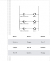
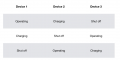
I haven’t figured all that out yet but, to give an example off the top of my head with using a battery: in the ‘operating’ mode the battery will be powering a 10W light; in the ‘charging’ mode it will be receiving about 14V DC from a mains charger, and in ‘shut off’ mode it will be doing nothing. Is that what you mean?n
No, you misunderstand my question.
Each state of the device requires some set of connections. You have not told us what those are, and we cannot determine that from what you have said. You question was about how to sequence it. My question is: sequence what?
A valid answer might be:
1. Running: Connect 12V to the red wire only.
2. Charging: Connect 12V to the blue wire only.
3. Idle: No power connected.
This would require two relays per device.
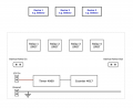
The reason why I’m not going down the microprocessor route is so I can also show it to one of my students and clearly point out the different functions being carried out by each section of the circuit. You can’t do that pointing to a monolithic processor chip.