8085 address question.....

Thread Starter

RRITESH KAKKAR

Joined Jun 29, 2010
2,829
I fixed it for you. See post #56. The file attached there has all you code in the format you need to enter it.
Yes, i have downloaded the file the problem was i am using a homemade PROM programmer...

Thanks for the help..!!
 

Thread Starter

RRITESH KAKKAR

Joined Jun 29, 2010
2,829
Hello sir,

I have connected all pull ups resistance to WR and RD pin of ROM and RAM...
LED was also connected as per schematic.
The Code in ROM was also corrected but still the the SOD was not working, I have connected my Buzzer to all Addr pin there was no sound coming tik ..tik...( square wave sound) as it was before.

I am using 4MHZ crystal and i have connected the SID pin directly to GND and the resets ckt was made by pull up Resistance of 5K and micro switch connected to GND.
 

Thread Starter

RRITESH KAKKAR

Joined Jun 29, 2010
2,829
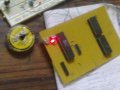
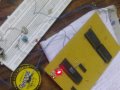
I am posting images of 8085 Board.
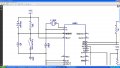
I have checked all connection are as per schematic and the reset circuit was with pull ups resistance and micro switch connected to GND.

Note:- I found that connecting ROM to board the code on it get changes, why I am using pull ups resistance also at RD and WR pin...
Please help.
http://www.youtube.com/watch?v=qF5gSjhEEM4
 

Attachments

Last edited:

BillO

Joined Nov 24, 2008
1,001
Hi Rritesh, without having your board myself, it's not going to be possible to help you much further. According to the assumptions I made about your programmer, the code and schematic I gave you should work.

There could be a bad device, a wiring error, a bad solder joint, or an incorrect assumption on my part. Any of those could cause this not to work.

:confused:
 

Thread Starter

RRITESH KAKKAR

Joined Jun 29, 2010
2,829
Hi Rritesh, without having your board myself, it's not going to be possible to help you much further. According to the assumptions I made about your programmer, the code and schematic I gave you should work.

There could be a bad device, a wiring error, a bad solder joint, or an incorrect assumption on my part. Any of those could cause this not to work.

Hi,

I don't understand why the code in ROM are overwritten as i am using pull ups resistance also...!!
due to ROM the output of 3 to 8 decoders are not going high as it should go.
 

Thread Starter

RRITESH KAKKAR

Joined Jun 29, 2010
2,829
Hi again,

I am using 5K or 10k resistance to Vcc not directly...!!
I was wrong...!!
the pin behind the group of wire was not clear visible. when i was testing it the WE pin of 2864 i.e. ROM was open, not connected to Vcc that's why my code in EEPROM was overwritten.

I have remove that problem Now i have checked code they were not over written and the SOD pin was blinking LED very fast ..
That mean it is working COOL..!!

soon i will post the video of it..!!
 
Last edited:

stahta01

Joined Jun 9, 2011
133
The R and C are part of an RC charging circuit that results in reset being true on power on. The switch is used to short the C resulting in resetting the MCU. The diode is used to drain the C on power off. Without the diode a quick power off to on cycle might result in no reset.

Tim S.
 

t06afre

Joined May 11, 2009
5,934
I am glad you got things working in the end. I have seen your prototype board for this project. If you follow these advices things will be much more easy for you
  • Avoid the bird nest structure. Keep things much more tidy
  • As far as possible keep the wires on one the same side as your components. And the solder joints on the other side.
  • Group signals together and use the same cable color for these signals. As an example The data bus one color, the address bus one color, and the control bus one color, and the same for power signals.
  • Experiment with the component placement to find the optimal solutions before soldering them onto to the board. And Also here keep things tidy. If the board is organized life will be much more easy for your. And your projects will also look better.
  • Always use cables with Multi-thread copper core. Single thread core wires are very fragile and tend to break for nothing.
For cables with different colors old printer cables (parallel port) may be a good source. But most electrical use some sort of color coding. I still pick up good cables then I come over them.And strip them for wires then needed
 
Top