74192 counter up/down

Thread Starter

findurmouth

Joined Oct 25, 2025
13
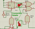
I am designing an up/down counter with a range from 00 to 99. The counter must stop at 99 when counting up, and similarly, it must stop at 00 when counting down. Does anyone has solution for this problem
 

WBahn

Joined Mar 31, 2012
32,703
Thanks for your advice. This is the image of my circuit View attachment 359684
It would be nice if the screenshot included the entire circuit instead of cutting off wires at the bottom and making us guess whether or not there is an inverter on the bottom circuit. A bit more neatness in the layout of the wires around counter chips would also be helpful -- you've got wires crossing wires, only to cross them again. Avoid crossing wires as much as possible, it will make your diagrams a lot easier to follow, which is a point that will not be lost on the grader.

Why are your up/down inputs being generated by LM358's configured as static comparators, and why does each one need it's own 5 V regulator?

What is the circuit currently doing and to what degree is it correct and incorrect?

What conceptual change would fix the misbehavior? Don't think so much in terms of how to implement the fix, but the idea behind fix. Break the problem down into small sub-problems and tackle them one at a time.

For instance, If the counter is rolling over after it reaches 99, the cause is that it is still getting an UP pulse when it is 99, so the conceptual fix is to somehow block the UP pulse from getting to the input of the counter when the current state is 99.

Next, think of how you could block the UP pulse in general. Don't worry about linking it to the counter state, just, in general, if you had a wire that was HI when you wanted the counter to count up and LO when you didn't, how could you use that signal to block the UP pulses from getting to the counter.

After that, think about how you could get information from counters to produce this "count-up-enable" signal.
 

Thread Starter

findurmouth

Joined Oct 25, 2025
13
My idea is the same as in this video, but so far I’ve only managed to implement the counting function. I still haven’t figured out how to stop the counter at 99 and 00.
 

WBahn

Joined Mar 31, 2012
32,703
My idea is the same as in this video, but so far I’ve only managed to implement the counting function. I still haven’t figured out how to stop the counter at 99 and 00.
Take it one piece at a time.

Let's consider just the stopping it from counting up from 99.

Q1) What signal causes the counter to count up?

Q2) What would happen if you could force that signal not to happen when the count value is 99?

Q3) Is there anything about the outputs of the counters that only happens when the count value is 99?

Q4) Is there a way to detect that special state of the counter outputs to produce a signal that is in one state only when that special state exists and is in the other state at all other times.

Q5) Is there a way to use that detection signal to force the signal identified in Q2 to not happen?
 

WBahn

Joined Mar 31, 2012
32,703
I tried connecting the logic gates together, and it successfully stops at 99. The remaining problem for me is stopping at 00View attachment 359747
You are on the right track, but your approach is needlessly complex. It is also susceptible to glitching.

Consider the case of when the count goes from 7 to 8.

0111 = 7
1000 = 8

All four output bits have to change and they won't change instantly all at the same time. They will change one at a time in quick succession. If it's a ripple counter, they will change from lsb to msb, but if it is a synchronous counter (which the 74192 is), then the order will be effectively random. Any sequence in which the msb goes HI before the lsb goes LO will result in a glitch in your detection logic. If that glitch can carry through to the counter's clock input, then you will get an extraneous clock event. Verifying that this can't happen is the burden that you accept when you decide to design asynchronous circuits.

It was pointed out to you earlier that TCU and TCD each go LO on the terminal count in the corresponding direction. Isn't what you are trying to do with your logic is determine that both counters are on their terminal count?
 

Thread Starter

findurmouth

Joined Oct 25, 2025
13
Thanks to help me in this problem. I tried connecting the TCU and TCD pins through an AND gate, and it seems to work. I’m not sure if this is the correct solution for this issue.1764542749243.png
 

WBahn

Joined Mar 31, 2012
32,703
I have another issue: the counter gets stuck at 99 and doesn’t count down the way I want.
[/QUOTE]

I think you need to spend some quality time with the 74192 data sheet. I just took a gander and the behavior of the TCU and TCD pins, and also the logic levels needed on various inputs to count up and down, are not quite as simple as I recalled (it's been about four decades since I've actually touched on of these chips). So, go read it carefully and then see what changes are required.
 

Thread Starter

findurmouth

Joined Oct 25, 2025
13
This is the state when the counter counts down to 00. I have a slight confusion in my initial idea. The counter should not be clamped at both ends. Instead, when it counts up to 99, it should not be able to count up anymore, and can only count down. My project is to design an occupancy counting system for a parking lot
 

WBahn

Joined Mar 31, 2012
32,703
This is the state when the counter counts down to 00. I have a slight confusion in my initial idea. The counter should not be clamped at both ends. Instead, when it counts up to 99, it should not be able to count up anymore, and can only count down. My project is to design an occupancy counting system for a parking lot
Why shouldn't it be clamped at both ends? Are you saying that it should be able to count down from 00 to 99?

Now, I realize that the parking lot scenario is really just window dressing on what is really a counter-design problem, but for that scenario, does it really make sense to simply cap the output at 99 but let it count down?

Let's say that it reaches 99. Then 21 more cars come in, but it is clamped at 99. Now 10 cars leave and the counter says that there are 89 cars in the garage. Is that meaningful? Wouldn't it be better to give some kind of persistent over-capacity indication, such as flash the 99 and leave it flashing (at 99) no matter what happens after that so that anyone looking at it knows that (1) at some point since the last reset the count tried to go over 99, and (2) there is no way to know how many cars are in the garage based on any number that the counter displays?

Again, your assignment is to implement a counter that has a couple of specific behaviors and the scenario is probably superfluous to that. But you might consider discussing these things, and how you might address them, very briefly, in your write-up. Graders (and more specifically instructors) look favorably on students that are thinking about the details and implications.
 

Thread Starter

findurmouth

Joined Oct 25, 2025
13
I'm sorry because my English is not good :confused:
My idea is that the parking lot has only 99 spaces. When all 99 spaces are occupied, a red indicator light will turn on to show that the parking lot is full. When the number of occupied spaces is less than 99, a green light will turn on to show that there are still available spaces.
Therefore, I am working step-by-step with a simple circuit first so that I can clearly understand my project.
1764652756868.png
i tried using a FF to switch from up to down when the counter reach at 99 but i don't think it's a good idea :(
 

Thread Starter

findurmouth

Joined Oct 25, 2025
13
1764656451418.png
Here is the current circuit diagram i have right now . When I simulate it, it works exactly the way I want. I’m sorry that I don’t know how to attach a video yet because this is my first time i use this forum.
 

ericgibbs

Joined Jan 29, 2010
21,390
hi find,
How and where are these two marked inputs connected.?
Are they normally High or Low logic when not activated???
E

Added: The Unused Clock input must be High in order to allow the Active Clock input to work.
EG 1861.pngEG 1860.png
 

Attachments

Last edited:
Top