Up/Down Counter (74192 & 555 timer)

Thread Starter

Franz Lord Memije

Joined Mar 13, 2017
12
Good day!

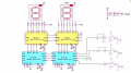
I'm making an up/down counter using 74192, 555 timer, 7447 and 7-segment LED. However, my counter starts at 1 but it should be in zero.

Please help me to know my error in 555 timer so that the display starts at 0.

Also, I want to use the down function but I can't figure out.

Here is the attached schematic diagram.
555.jpg
Thanks!
 

Thread Starter

Franz Lord Memije

Joined Mar 13, 2017
12
@ericgibbs it is common anode LED. I already refered to that schematic. However, our professor told us to use a 555 timer and 74192. Originally, the schematic diagram I uploaded is the first digit of 3-digit scoreboard.
 

WBahn

Joined Mar 31, 2012
32,703
Look closely at your timer output just as your simulation starts (I'm assuming that you can run such a transient simulation in whatever tool you are using).

I suspect that there is a transient that results in the line from the timer output being momentarily HI.

Why do you have the pullup on the output? The 555 has an active output for both states. My guess is that the initial operating point pulls the output like HI since the initial state of the timer is unknown.

You might remove the pullup (or even make it a pulldown).

You might also put a switch on the reset line (one of the timer and one on the counter) and see if, after the simulation gets running, you can manually reset the system.

If you can, then this is probably where your issue lies. If you can't, then the problem probably lies elsewhere. In either case, you get a pointer in the direction you need to go to find it.

This might also be an opportunity for you to learn how implement a power-on-reset feature.
 

JoeJester

Joined Apr 26, 2005
4,390
While it's definitely a noteworthy observation, I don't think it explains the simulation problem since the supply voltage is almost certainly treated as an ideal supply.
However, I always start my simulations from zero, just like throwing a power switch.

VF1 shows a 5 volt supply with a 1 milliohm internal resistance without
VF2 shows another 5V supply with a 1 milliohm resistance, feeding a not shown circuit with decoupling.

555-problem.png

Now I don't know a thing about multisim's settings or if they do anything like LT Spice does with their supplies. I set the internal resistances on voltage sources. When I try to get closer to reality, I look up the supply specifications.

I only tested the clock in this circuit. I haven't completed the rest of the circuit, yet, but I have used a power up reset on the counters to circumvent that type problem.
 

dendad

Joined Feb 20, 2016
4,635
To count up and down, have a pull up resistor on both the UP and DOWN pins and feed the clock to one OR the other input as required.
 

Thread Starter

Franz Lord Memije

Joined Mar 13, 2017
12
Hello guys!

This is now my complete schematic diagram for a scoreboard. There are three buttons for UP dedicated for an increment wherein it adds 1, 2 or 3. Also, I have added a RESET and minus 1 but it's not working :(

The reason why I used two 555 timer on +2 and +3 so that I could have exact number of pulses that will trigger UP. Or is there other way than that?
reference: https://electronics.stackexchange.com/questions/86085/limit-number-of-pulses-from-555-or-similar

Although my circuit is working but still when I start the simulation, it still displays 001 instead of 000. Do you have any suggestion other than a RESET?


Thanks!
Final Final schem.png
 
Last edited:

ericgibbs

Joined Jan 29, 2010
21,390
Hi Franz,
Are you assuming that the U25B inverter input is pulled up High , before minus1 button is pressed.? Add a pullup resistor, say 1k.
E
 

ericgibbs

Joined Jan 29, 2010
21,390
pull up resistor after the inverter

The pull up should be before the inverter.

EDIT:

When using mechanical switches to drive logic inputs you should use Schmitt inverters and some switch de-bounce. See my earlier circuit post.
 

Attachments

eetech00

Joined Jun 8, 2013
4,704
Hi

You don't need all those 555 timers.You only need 1 clock.
You don't have the 192 up/down input circuited correctly.
The reset inputs are not correct.

What kind of "scoreboard" is this. Please explain how it is supposed to work from a user perspective.
 

Thread Starter

Franz Lord Memije

Joined Mar 13, 2017
12
@ericgibbs I have added an pull-up and a schmitt inverter however the circuit is not working.

@eetech00 hello!

This is a basketball scoreboard wherein I need to have a dedicated button for 1pt, 2pts and 3pts. When a button is pressed, the display should automatically increase its score depending on the point dedicated to the button.

Also, there must be a button for a minus 1point and a reset.

Please guide me on how to use 555 timer since this is the first time I'm using it and it has not been discussed by professor. I have just based my circuit on some Up/down counter circuits that I have seen and I'm having a hard time on how to put a +2pts and +3pts since most Up/down counter that I've seen only has +1 or -1.

I don't know what is wrong with the UP/DOWN input of 74192 can you please tell me so that I could revise it?

Also, how come that the input of reset button is wrong? It works fine when I simulate it.. Please guide me.

Thank you!

Everyone, please bear with me since I want to fully understand what I'm working on. Thank you :)
 
Last edited by a moderator:

dendad

Joined Feb 20, 2016
4,635
D1 should be a resistor, not a diode.
I'd replace the Down switch circuit with something like this...
http://hyperphysics.phy-astr.gsu.edu/hbase/Electronic/setreset.html
This ensures you only get 1 pulse per button push. Make sure the UP and DOWN pins rest in the high state. I think that is the correct way from memory. If they rest low, it may not work.
The same sort of thing could be used for the reset too if you wanted.

And trying to work out the 555/gateing circuitry... I haven't had enough coffee for that ;)
 
Top