5V Regulator issue in soft switch circuit

Thread Starter

Omri284

Joined Apr 18, 2020
21
Hi,
Not sure if this is the right place to ask, please correct me if i'm wrong :)
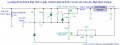
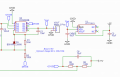
I built a circuit according to the added schematic(also added PCB), it is a soft on/off switch with delay for the off side.
My problem is that the regulator I took - HT7150-3 - doesn't put out 5V as expected. I replaced it with an LM7805 and the circuit worked fine.
I want to know what the problem is before and if I can fix the current situation. Mabye the max current limit of the chip?
schematic.png

PCB(The regulator's Vin is connected to the Vout by intention, and the regulator's output doesn't show 5V):
PCBHT7150.png

HT7150-3 datasheet

Thanks,
Omri.
 

Attachments

dl324

Joined Mar 30, 2015
16,846
Welcome to AAC!
My problem is that the regulator I took - HT7150-3 - doesn't put out 5V as expected. I replaced it with an LM7805 and the circuit worked fine.
I'm surprised that either part worked. LM7805 specify a minimum load current of 5mA. The HT7150-3 specifies 1mA; maybe it's pickier about the specifications being followed.

Didn't give your layout a close look, but you could make the routes to the LED and resistor cleaner:
1587238543256.png
You can move the LED up if you want it in the same position. I was too lazy because it was awkward to make the edits in a photo editor.

vs your layout:
clipimage.jpg
 
Last edited:

iimagine

Joined Dec 20, 2010
511
Should be fine, the worst case is that if the minimum load current of the 7805 is not met, then it wont be on. Other then that, its just a latch.
 

Thread Starter

Omri284

Joined Apr 18, 2020
21
I'm surprised that either part worked. LM7805 specify a minimum load current of 5mA. The HT7150-3 specifies 1mA;
Thanks for the reply!
So what do you suggest in that case? lower minimum load regulator? put a load at its output with this current?
The currents I saw are very low(less than 1m), despite that the LM7805 worked.
Thanks for the correction in the PCB, will take care of that and other bad wiring there.
 

dl324

Joined Mar 30, 2015
16,846
So what do you suggest in that case? lower minimum load regulator? put a load at its output with this current?
That would be the most straightforward. Another option is to connect the supply to the load it will be supplying.
The currents I saw are very low(less than 1m), despite that the LM7805 worked.
The specifications in the datasheet are to guarantee correct operation. LM317 specify a minimum load current of 10mA, but I've had many work with less. I've also had one that wouldn't work with a load less than 20mA. It was an outlier, but what can you do?
Thanks for the correction in the PCB, will take care of that and other bad wiring there.
I review my PCB layouts for optimizations several times before I consider making a board.
 
The HT is like 30mA and the LM 1.5A. The minimum load spec hides sometimes. You didn't show a ground on your schematic for the regulator. Something else that's usually missed is that the heat sink should be designed for short-circuit current.
 

Thread Starter

Omri284

Joined Apr 18, 2020
21
Ok, I tried a few things, and it worked, trying to figure out why and if i'll have problems with it :)
I added a pull down resistor - 100k - going down from the regulator's output to gnd in order for it to have the minimal current and it did worked as expected now, so did the circuit.
The current flowing through it should be 50uA(5/100k) which is far from the minimum mentioned here(1mA) - how come its enough?
Something I do not understand is why it didn't work with 2k resistor - that suppose to be ~2mA - with this one Vout was turned on but turned off as soon as I left the push button.
Any thoughts?
Thanks.
 

Thread Starter

Omri284

Joined Apr 18, 2020
21
Another issue which is more important that I have - I get a spike in Vout(goes down and up) when pressing the button momentarily when already turned on:
1587386243988.png

This happens becuase the voltage in the P-gate jumps over the threashold and tunes the P-fet off, to solve this I removed this resistor:
1587386646560.png

Now in my simulation, the P-fet doesn't close and everything works fine, but in reality a few seconds after it is turned off it turns back on, and i'm stuck at this point.
I would prefer to leave the resistor where it is and find a solution to the Vout voltage overshoot.
Thanks
 

Attachments

dl324

Joined Mar 30, 2015
16,846
The current flowing through it should be 50uA(5/100k) which is far from the minimum mentioned here(1mA) - how come its enough?
It may be sufficient for the particular part you're using, but conservative design methodology dictates that you design for the worst case situation. If it's a one off design, it could be okay. If you ever needed to replace the regulator, the design might not work.
 
Top