 Facebook
 Google
 GitHub
 Linkedin
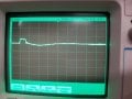
This is a robotics project where we are driving a pump with a power MOSFET that is driven using a PWM signal to control pump speed. The power source is a 6-Cell Lithium Ion battery pack. Both the pump and the DC/DC converter are connected to the high side of the battery pack. When we are not switching the pump (at either zero or full power) the 5V output is clean. However, when the PWM signal switches, we see spikes in the 5V output reaching just over 8V for ~4us (Single 5V Spike.jpg, 5V with pump switching on then off.jpg). We are hoping to use the 5V output to power a Raspberry Pi Zero W, which is rated to handle up to 5.25V.
Looking at the battery voltage for a 25% duty ratio, the battery voltage begins dropping (Battery Voltage.jpg), and then peaks about 4V above nominal when the pump is switched off (we have a flyback diode to minimize this voltage spike).
We have tried smoothing the 5V output with a low-pass filter (1250Hz cutoff) and a 5V zener diode. We are using a small computer fan for a load.
Is this typical behavior for a DC/DC converter when the input voltage is changing? Would there be a way of mitigating these spikes. Alternatively, are these very short spikes in voltage acceptable for the Pi Zero?
Attachments
-
 142.7 KB Views: 7
 -
 133.8 KB Views: 6
 -
 127.7 KB Views: 6


