5S BMS strictly for undervoltage protection?

Thread Starter

LikeTheSandwich

Joined Feb 22, 2021
164
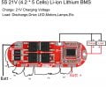
I'm considering a 5S BMS like this one from Amazon. Let's say I have a project and I want to use a powertool battery which is itself a 5S battery. I have no access to the balance wires inside it. I want undervoltage protection. Could I use that BMS linked at the start? If it requires balance connection leads, could I just 10k or whatever resistors to create a voltage divider, such as in the below picture? To clarify, it will never be used to charge, only for protection. Would this, at least theoretically, work? The current draw over time would be extremely small, less than .5mA, and even lower if I use 100k or 1M resistors.
 

Attachments

MisterBill2

Joined Jan 23, 2018
18,519
Unless you have cheap junk power tools it does not seem reasonable to redesign the battery packs. And for those cheap junk power tools it is probably not worth the effort. In the several battery packs that I have opened there is not much room to add anything inside.
 

Ya’akov

Joined Jan 27, 2019
9,165
Unless you have cheap junk power tools it does not seem reasonable to redesign the battery packs. And for those cheap junk power tools it is probably not worth the effort. In the several battery packs that I have opened there is not much room to add anything inside.
The way I understood the TS, he is wanting to use the power tool battery to power something else. My expectation is that the battery already has the BMS in it, and there is no need to add anything, but I don't know which brand it is, so...
 

Thread Starter

LikeTheSandwich

Joined Feb 22, 2021
164
The way I understood the TS, he is wanting to use the power tool battery to power something else. My expectation is that the battery already has the BMS in it, and there is no need to add anything, but I don't know which brand it is, so...
Milwaukee. They have direct access to positive and negative of the pack.
 

Thread Starter

LikeTheSandwich

Joined Feb 22, 2021
164
Unless you have cheap junk power tools it does not seem reasonable to redesign the battery packs. And for those cheap junk power tools it is probably not worth the effort. In the several battery packs that I have opened there is not much room to add anything inside.
Not messing with the pack, BMS would go inside project, hence why I'd only have access to positive and negative.
 

Ya’akov

Joined Jan 27, 2019
9,165
You don't need a BMS to deal with overdischarge. You have three options.

You can do that the tools do and listen to the battery for a low voltage signal, and shut it off.

You can use an under voltage module of some sort (like this one, that seems a bit bulky but very popular: https://www.amazon.com/Digital-Battery-Low-Voltage-Protection/dp/B07929Y5SZ).

You could make your own circuit you were inclined to do the job, if you were inclined.

In any case, you will not be charging the battery, so a BMS is overkill in a way that makes it just the wrong thing.
 

Thread Starter

LikeTheSandwich

Joined Feb 22, 2021
164
You don't need a BMS to deal with overdischarge. You have three options.

You can do that the tools do and listen to the battery for a low voltage signal, and shut it off.

You can use an under voltage module of some sort (like this one, that seems a bit bulky but very popular: https://www.amazon.com/Digital-Battery-Low-Voltage-Protection/dp/B07929Y5SZ).

You could make your own circuit you were inclined to do the job, if you were inclined.

In any case, you will not be charging the battery, so a BMS is overkill in a way that makes it just the wrong thing.
That thing is bulky as you've said, it's also way more expensive. Back to my original question, will my idea work?
 
Last edited:

MisterBill2

Joined Jan 23, 2018
18,519
This thread has gone beyond confusing as far as I see. In post #1 we see a picture of the internals of a battery pcak management board with resistors penciled in where batteries would be connected.
Then later we get remarks that only the positive and negative are accessible. And then concerns about overcharging and under-voltage. Or is the PCB in post #1 related to some other project??
Running a project off of a battery pack intended for a different purpose is always a bit of a risk. There are a number of voltage monitoring circuits around, the simplest of them all uses one transistor and LEDs and some resistors. The green LED is not only the activity indicator, it is also the voltage reference. The red LED goues from off to full brightness over the range of less than two volts. Unfortunately I did not save a copy of the circuit and I do not recall if the transistor was PNP or NPN. But it was a bipolar silicon device. So a warning light might be all that is really needed.
 

Thread Starter

LikeTheSandwich

Joined Feb 22, 2021
164
This thread has gone beyond confusing as far as I see. In post #1 we see a picture of the internals of a battery pcak management board with resistors penciled in where batteries would be connected.
Then later we get remarks that only the positive and negative are accessible. And then concerns about overcharging and under-voltage. Or is the PCB in post #1 related to some other project??
Running a project off of a battery pack intended for a different purpose is always a bit of a risk. There are a number of voltage monitoring circuits around, the simplest of them all uses one transistor and LEDs and some resistors. The green LED is not only the activity indicator, it is also the voltage reference. The red LED goues from off to full brightness over the range of less than two volts. Unfortunately I did not save a copy of the circuit and I do not recall if the transistor was PNP or NPN. But it was a bipolar silicon device. So a warning light might be all that is really needed.
The BMS would be inside of a project, let's say a flashlight, and the battery is external and removable, so I'm not concerned with overcharging, just over discharging. The BMS exists only to serve ultimately as a low voltage cutoff, no other function necessary. That's why I would be using the resistors to create a voltage divider, so the BMS would think all the individual cells are connected, assuming it won't function properly without said connections.
 

MisterBill2

Joined Jan 23, 2018
18,519
There are certainly some much simpler battery cutoff circuits around. Less expensive to build, as well. And also smaller.
Really, a low voltage cutoff could be part of the power switching circuit for the project.
 

Thread Starter

LikeTheSandwich

Joined Feb 22, 2021
164
There are certainly some much simpler battery cutoff circuits around. Less expensive to build, as well. And also smaller.
Really, a low voltage cutoff could be part of the power switching circuit for the project.
I've looked, and everything I've seen is just more effort than I would ideally like. And less than $4 for this board, is really quite inexpensive. To build one, the ones I've seen require numerous components, and to build it economically, I would have to spend a lot more money gathering parts in the 10s or hundreds largely, to make it work. I could quite easily do it with an ATTINY85 but I'd also have to put in a buck converter. I haven't really seen anything easy or simple at all to give me low voltage cutoff for 5S equivalent (probably 15V). The closest I could come up with is using a relay, one with a separate voltage trigger like this one from Amazon since I actually own a few of those. But I'd prefer some electronic option if I can find one.
 

Thread Starter

LikeTheSandwich

Joined Feb 22, 2021
164
It works fine with 5 10k resistors. I also experimented as one might intuit, having one resistor lower value allows for reduction in apparent voltage, so it gives a lower read voltage across what would be one of the cells, effectively giving it a higher cutoff voltage. I think I'll make a new thread about my findings to help others.
 

jdesbonnet

Joined Apr 7, 2022
1
That thing is bulky as you've said, it's also way more expensive. Back to my original question, will my idea work?
Also beware that board draws something like 60mA when the battery pack is under-voltage and relay is off. It will kill the pack if left connected in a matter of a day or two. Probably find for solar charging applications where the battery will get recharged before the voltage drops into damage territory.
 
Top