Protoboard Project 555 Wide Range Oscillator

Thread Starter

Wendy

Joined Mar 24, 2008
23,421
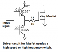
Sorry I've had this thought rattling around in that empty space between my ears. I haven't built it yet but I have all the parts to:

555 Oscilator.png

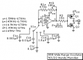
when I finish this will be a completed project and I will start a new thread, for now I am opening the subject for ideas and iterations. There will be a 3D printed box to go with it, and if I can get it to work it a frequency counter.
 

Attachments

Last edited:

Ian0

Joined Aug 7, 2020
9,808
One of your MOSFETs is upside down. I don’t know which one, as I don’t know if you intended it is an inverting output, or a complementary source-follower.
(a low-side MOSFET gate driver would make a nice output buffer)
 

Alec_t

Joined Sep 17, 2013
14,313
I think Q1 is the right way up (judging by the body diode), but the D and S markings are the wrong way round. There will be some shoot-through during the on/off state transitions.
 

DickCappels

Joined Aug 21, 2008
10,170
At times I have put a small resistor in series with each drain to limit the short circuit current during switching. That can probably be also done by the selection of the MOSFETs so their RdON is high enough.
 

Tonyr1084

Joined Sep 24, 2015
7,899
Did something quite similar. Only instead of a rotary switch I used dip switches. It's possible to select one of four caps or a combination of each, all the way up to all of them. Off hand I don't have the schematic handy. It's somewhere. Also featured on this board is the IC socket where you can put much larger caps into the circuit. With all the dip switches open only the applied capacitor will affect the circuit. If the desired frequency is a little too high it's possible to switch into the circuit some of the other caps and slow down the clock rate. If I locate the schematic quickly I'll post it.
IMG_2974.jpg
 

Thread Starter

Wendy

Joined Mar 24, 2008
23,421
I have the same kind of breadboard stock, and I have updated my schematic mistake. I will probably use a protoboard for this next design, since soldering is such a pain for me.
 

DickCappels

Joined Aug 21, 2008
10,170
You have me stumped. Why all those diodes on the adjustable output?

Edit: Is there a chance of hurting Q3 by having it try to drive all those diodes with more than 2.5 volts?
 
Last edited:

Thread Starter

Wendy

Joined Mar 24, 2008
23,421
Perhaps I should have drawn this schematic differently, if you look very close the diodes are not connected to the output variable output. The diode chain only crosses the variable output without actually making contact, the combined drop of all those diodes should be around 3.6 volts. Which is what a TTL output should be. Vcc is defined on the protoboard drawing, which is 12 volts. I plan on playing with the actual voltage on Vcc, I may use an external power supply instead of batteries.
 

Ian0

Joined Aug 7, 2020
9,808
Just a thought on the logic level output:
The CD4050 will run off a 5V supply and take an input of up to 18V, and each section will drive two TTL loads.
 

Thread Starter

Wendy

Joined Mar 24, 2008
23,421
I may use 8 AA batteries, haven't decided yet. When I start designing the 3D printed box, that's when I will make the final decision.
 

Thread Starter

Wendy

Joined Mar 24, 2008
23,421
So I have 3D printed a case for this project, and now I am working on the protoboard again. I tried this one:

Wide range 555 oscillator.png

the mosfets were a total bust, they loaded down the CMOS 555 to the point where it was not usable. Interestingly, I tried a 7555 and a TS555CN, the TS555CN blew the 7555 out of the water. Now I will addition BJT's to see if they work better. I will let you know.
 

Audioguru again

Joined Oct 21, 2019
6,690
Mosfets have a very high gate to source capacitance that is a heavy load at high frequencies.
Usually a pair of transistors (complementary emitter-followers) is used to drive high frequency Mosfets.
 

Attachments

Thread Starter

Wendy

Joined Mar 24, 2008
23,421
If I am going to use BJT transistors I will use only BJT transistors. Latest brain part:

Wide range 555 oscillator #2.png

I will live with the shoot through.
 
Last edited:

Audioguru again

Joined Oct 21, 2019
6,690
The Cmos 555 has a rail-to-rail output only when the load current is almost zero. The common-emitter transistors you used need a HUGE base current (10 times the collector current) to saturate. The huge current at the output of the Cmos 555 reduces its output voltage swing.
Emitter-followers do not have a huge base current because they do not saturate, instead they amplify with the low base current determined by the high hFE beta.
 
Top