Protoboard Project 555 Wide Range Oscillator

Thread Starter

Wendy

Joined Mar 24, 2008
23,421
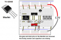
At 12 volts which is what I am planning to use for this circuit, it should have plenty of drive as well as rail to rail. I am planning to drive the transistors with 20ma which should be plenty to turn them completely on and off. I tried to be up front what's the results of my circuits so we shall see.
 
Last edited:

Audioguru again

Joined Oct 21, 2019
6,692
Hi Wendy, your circuit idea is fine.
I see that with a 12V supply the Cmos 555 can produce an output low of 50mA (!) at 2V max and produce an output high of 10mA at 10.5V minimum. Then it packs a lot of current when its supply voltage is 12V.
 

Thread Starter

Wendy

Joined Mar 24, 2008
23,421
I am my own worst enemy on this project, between using parts that are in the wrong values and other brain farts, it has taken a lot longer than I anticipated. The 7555 would not come up with a clean square wave no matter how I tried here is the wave form I got with an unloaded circuit both the resistors to the transistors and the transistors were removed.

7555.png 555.png

the second image is a stock 555. I still need rail to rail to make the square wave 50% symmetry. But I can work with the 555. So it is back to the drawing board, I will relay this board out try it a different way. More to come. I have think I have finished most of this 3D part of this project, it is good to get back to the electronics portion.
 
Last edited:

Thread Starter

Wendy

Joined Mar 24, 2008
23,421
I did I wanted to remove the load from the 7555 circuit to see if that was causing the distorted square wave. The 7555 waveform shown above is without a load. If you don't get a good way for him to begin with how are you gonna get it to work later? Even though it is a power hog I am going to try using a 555 instead.
 

Thread Starter

Wendy

Joined Mar 24, 2008
23,421
I just knew someone was going to bring that up. Yes I did compensate the probe since it never goes anywhere else but this is still a scope you only have to do it once (because I knew this issue would come up I checked it on the scopes built-in compensation output). The only difference in the two way forms shown is the chip used, one is flat and the other is not. I have got a new layout drawn, when I have gotten it implemented I will post the results.
 

Audioguru again

Joined Oct 21, 2019
6,692
The Cmos 555 has a fairly low max output current that takes time to charge the high gate-source capacitance of the very high power Mosfets. The old original 555 has a max output current much higher than Cmos 555s.
The breadboard has problems:
 

Attachments

Thread Starter

Wendy

Joined Mar 24, 2008
23,421
That design is history, I'm using some techniques I have developed in the past for the next iteration.
 
Top